

The 2024 technical report for the Clayton Valley Lithium Project in Esmeralda County, Nevada, USA presents a feasibility-level process design for a phased lithium production plant based on hydrochloric acid leaching, direct lithium extraction, and chlor-alkali integration.
Report context
This NI 43-101 Technical Report on the Feasibility Study documents the recovery methods and process design for the Clayton Valley Lithium Project, dated 29 April 2024. The process design is based on testwork discussed in Section 13 of the report and is focused on Project Phase 2 at a nominal plant capacity of 15,000 t/d. The design incorporates a staggered start-up approach, with Project Phase 1 operating at 7,500 t/d prior to the installation of additional equipment and parallel trains for Phase 2. A Project Phase 3 expansion to 22,500 t/d was also evaluated, with additional equipment to be included as a separate plant facility.
Processing route
Feed Handling and Size Reduction
ROM claystone will be conveyed from the mine to a covered feed material stockpile equipped with a stacker/reclaimer system. Material is passed through a roll crusher to break down large size fractions, then conveyed to two attrition scrubber units where it is mixed with neutral-pH process water and disaggregated into a slurry. The slurry is discharged onto two single deck vibrating screens with an aperture of 0.85 mm (20 mesh). Oversize and tramp material is temporarily stored and periodically transferred to the tailings disposal conveyor, while screened undersize slurry gravity flows to leaching pump boxes.
Leaching and Neutralization
The leach circuit consists of two identical trains, each with a pump box, slurry heat exchanger, and four leach tanks. Leaching is conducted at atmospheric pressure and 60°C using hydrochloric acid as the dissolution agent. The screen undersize slurry is pumped through a slurry-slurry spiral heat exchanger to recover energy from the leach discharge, pre-heating the fresh slurry to approximately 35°C. Hydrochloric acid is added to the first leach tank at a ratio of 10.4% w/w to solids. Process water is added to achieve 33% w/w solids in the slurry. The 10 m diameter × 12.5 m high leach tanks are agitated, covered, and sized to provide one hour retention per tank, four hours total per train, operating in cascade.
Leach discharge from both trains passes through spiral heat exchangers and overflows into a single agitated surge tank where sodium hydroxide adjusts the slurry to pH 7. Neutralized slurry at approximately 30% w/w solids is pumped to the tailings filtration area.
Tailings Filtration
The tailings filtration area consists of two parallel filtration trains, each with a buffer tank distributing slurry to three filter feed tanks, each feeding two filter press units. The design considers eighteen 2.5 m × 2.5 m filter press units including two standby units. Filtrate is collected as PLS in the tailings filter filtrate tanks for lithium recovery. Filtered tailings cake is combined with centrifuge residue from the impurity removal stage and transported by belt conveyors, fifteen grasshopper units, and a mobile radial stacker to the dry tailings storage facility.
Lithium Ion Exchange
PLS is pumped to the PLS surge tank which overflows to the PLS pond, providing 12-hour surge ahead of the IX circuit. Forced aeration at the PLS pond allows precipitation of ferric compounds. PLS is pumped from the surge tank to the lithium IX columns consisting of 24 trains of three columns, totalling 72 units in lead-lag arrangement. Barren solution discharges through safety screens that scavenge lost resin, and collected resin is used for start-up loading and make-up during operation. Barren solution is pumped to the centrifuge precipitation tank.
Loaded resin is eluted, with eluate passing through safety screens to scavenge lost resin before gravitating to the eluate tank and pumped through polishing filters to the softening system. Resin specified in the plant design does not require a regeneration stage.
Softening Ion Exchange
The eluate enters the softening circuit where divalent cations (Ca²⁺, Mg²⁺, Ba²⁺, Sr²⁺, Fe²⁺, Mn²⁺) are exchanged onto resin while lithium passes through. Resin regeneration is performed using a salt solution. Regeneration backwash and weak waste solutions are returned to the process. The lithium-rich softening effluent is pumped to the RO system.
Reverse Osmosis
The softening effluent is filtered and treated in a two-pass RO system to concentrate and recover lithium and ensure permeate purity. The system consists of eight 1 μm cartridge filters, eight first-pass two-stage RO skids, and eight second-pass two-stage RO skids. First-pass reject is concentrated in dissolved ions including lithium and directed to the UHP-RO system. Second-pass reject is recycled to RO feed, and second-pass permeate reports to the permeate make-up tank for reuse.
DLE Discharge Impurity Removal
Discharge solution from the lithium IX circuit is pumped to the centrifuge precipitation tank where sodium hydroxide increases pH to 12, precipitating calcium and magnesium impurities. The slurry at approximately 1.5% solids is decanted in a 12 m diameter centrifuge feed thickener. Clear solution overflows to the centrate tank, and underflow at 10% w/w solids is centrifuged. Two centrifuges produce Ca/Mg precipitates at approximately 40% w/w solids, discharging onto the tailings conveyor. Centrate combines with thickener overflow and is pumped as feed to the chlor-alkali plant.
Lithium Concentration and Precipitation
The RO concentrate at an estimated 2.4 g/L Li undergoes further concentration via UHP-RO at 120 bar, reaching up to 130,000 mg/L TDS on a sodium chloride basis. The UHP-RO system consists of two skids/trains with high pressure and centrifugal pumps. Permeate is reused and reports to the RO permeate make-up tank.
The UHP-RO reject, at an estimated 4.1 g/L Li, is concentrated with the mechanical vapour recompression evaporator, consisting of three skids with three vessels each, total evaporation capacity 3,100 m³/d. The refined stream is pH-adjusted to 5 with HCl before evaporation. Distillate is reused as RO water.
The concentrated liquor at 9.7 g/L Li passes through final polishing to remove residual calcium and magnesium hardness. The liquor enters the CIX circuit at approximately 84 m³/h, distributed to three softening vessels with 7.4 m³ resin capacity each. The CIX circuit is designed to provide discharge concentrations below 1 mg/L calcium and magnesium within a 2.8-hour cycle time. Hydrochloric acid, sodium hydroxide, and RO water regenerate and rinse the resin. Weak waste solution is recycled to the RO raw water system, and high strength waste returns to the surge tank.
Lithium Carbonate Production
Effluent from the CIX circuit reports to a series of stirred lithium carbonation refining reactors where lithium is precipitated as lithium carbonate using 28% w/w soda ash solution. Four 7.6 m³ refining reactors are distributed in two modules with a capacity of 930 m³/d per module. Precipitation occurs at 80°C, maintained by direct steam injection. The reactors are highly automated to ensure high yield and quality.
The resulting lithium carbonate slurry at an estimated 3% w/w solids undergoes dewatering and washing through a single-stage peeler centrifuge to reduce water content to approximately 20% w/w. Blowdown solution from the centrifuge contains important lithium levels and reports to the mother liquor storage tank before recycling to the PLS surge tank. Centrifuge rinsing solution containing soda ash and lithium is recycled to the soda ash solution preparation tank. Two operational and one standby peeler centrifuge units with a capacity of 1.8 t/h each are considered in the design.
Lithium Carbonate Drying and Loadout
The washed lithium carbonate filter cake is conveyed by screw conveyor to an indirect electric rotary dryer with a capacity of 4 t/h. Dried lithium carbonate is discharged at 160°C to a blower, which pneumatically transports the material to a transfer bin feeding a magnetic detector and cage mill. The cage mill breaks up agglomerates formed in the dryer. Dust generated is captured in a baghouse and discharged into the transfer bin. Fine lithium carbonate is stored in a silo, packaged into 1 m³ bags, and loaded into intermodal shipping containers.
Chlor-alkali Plant
The chlor-alkali unit consists of two parallel trains. Process discharge from the lithium IX is mixed with depleted solution and concentrated to 300 g/L sodium chloride. The concentrated salt solution is purified through filtration, precipitation, and ion exchange steps to remove magnesium, calcium, lithium, boron, and aluminium. Purified salt solution passes through a heat exchanger before feeding electrolysers.
Each cell is divided into anode and cathode sides separated by an ion exchange membrane. Salt solution and 30% w/w caustic are fed to the anode and cathode chambers respectively. Hydrogen and chlorine gas feeds hydrochloric acid synthesis to produce 35–36% w/w HCl solution. Caustic is diluted and recycled to the electrolyser with excess used in the process plant.
Hydrochloric acid at 36% purity is produced at the chlor-alkali plant and pumped to storage tanks providing five days capacity. During start-up, HCl arrives by bulk tanker truck. Sodium hydroxide at 32% purity is produced and stored in two tanks with five days capacity. During start-up, NaOH arrives by bulk tanker truck.
Antiscalant is dosed at 5 mg/L to the RO feed water from drums using peristaltic pumps.
Water System
The water system consists of two separate circuits: make-up water and process water. Raw water is supplied from a new well to the raw water tank, then filtered and treated in an RO system. RO permeate is stored in the RO/fire water tank. Primary RO water usage is as permeate make-up for elution at the lithium IX system and reagent dilution in the IX, softening, and CIX systems. Raw water requirement has been estimated at 221 m³/h.
The plant design contemplates two process water circuits. A neutral-pH process water (PW1) circuit and a high pH (~12 pH) process water (PW2) circuit. PW2 is generated from the chlor-alkali plant and tailings filtrate. Excess PW2 is neutralized with hydrochloric acid and combined with raw water RO and process water RO reject streams to generate PW1. PW1 is used in the chlor-alkali plant, leaching tanks, and wash water in the tailings filters.
Excess neutralized water is treated in a process water ultrafiltration and RO system consisting of six UF filters and six two-pass/two-stage RO skids, recycling excess water back to the system.
Steam, Air, and Power
Steam is supplied from an electric steam boiler for process heating, primarily for the leaching circuit and lithium carbonation tanks. Two dedicated process air compressor systems provide high pressure compressed air for air squeeze on pressure filters and blowdown air on IX columns. Instrument air is used throughout the plant.
Power for processing facilities will be supplied via power lines from the electrical grid. Total power requirements are 113.75 MWh for Project Phase 1 and 174.69 MWh for Project Phase 2, with the chlor-alkali plant representing the largest consumer at 78.0 MWh and 120.0 MWh respectively.
Key reported parameters
| Design Parameter | Units | Project Phase 1 | Project Phase 2 |
|---|---|---|---|
| Nominal processing rate | t/d | 7,500 | 15,000 |
| Annual processing rate | t/y | 2,737,500 | 5,475,000 |
| Plant availability | % | 92 | 92 |
| ROM feed moisture | % | 20 | 20 |
| Processing plant feed rate (dry) | t/h | 340 | 680 |
| Leach temperature | °C | 60 | 60 |
| Leach retention time | h | 4 | 4 |
| Leach tanks/trains | units | 4 / 1 | 4 / 2 |
| Acid consumption | t/t feed | 0.104 | 0.104 |
| Filtration filters | units | 9 | 18 |
| Filtrate cake water content | wt % | 35 | 35 |
| PLS to lithium recovery | m³/h | 1,041 | 2,083 |
| Lithium solution feed to RO | m³/h | 99 | 198 |
| Solution feed to chlor-alkali plant | m³/h | 1,130 | 2,260 |
| Lithium carbonate production | t/d | 35.6 | 71.2 |
| Average lithium grade in feed | % | 0.113 | 0.113 |
| Lithium leach recovery | % | 80.2 | 80.2 |
| Overall lithium recovery | % | 78 | 78 |
| Total make-up water | m³/h | , | 221 |
| Chlorine production | t/d | , | 1,234 |
| Hydrogen production | Nm³/h | , | 16,607 |
| NaOH 100% production | t/d | , | 1,387 |
| HCl concentration (min) | % w/w | , | 36 |
| Electrolyser units | , | , | 24 |
| Cell elements per electrolyser | , | , | 86 |
| Salt storage | d | , | 5 |
Project website: https://noramlithiumcorp.com/resource/clayton-valley/
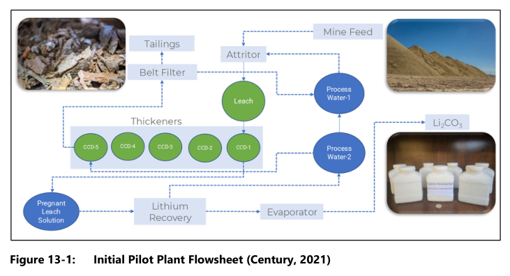
Project website: https://www.centurylithium.com/news/2021/cypress-development-provides-update-on-clayton-valley-lithium-projects-pilot-plant-status
Technical qualifications
This report presents a feasibility-level process design; it does not constitute a pre-feasibility or definitive feasibility study. Several elements of the process description are protected under patent application by the company, and the generalized descriptions of the DLE processes are proprietary to the company and its intellectual property license. The process design is based on testwork discussed in Section 13 of the source report, and the design parameters show design criteria rather than demonstrated operating performance. Power requirements are presented as design basis values in MWh, the unit used in the source table, and may be subject to refinement.
The report notes the process plant design is based on maximizing the use of the chlor-alkali plant and infrastructure limitations related to water and power availability. The process water RO system includes six UF filters and six two-pass/two-stage RO skids; the number of RO skids in the main concentration section is eight first-pass and eight second-pass units. Water balances include unquantified elements in certain circuits. The raw water requirement is described as estimated at 221 m³/h.
Source: Clayton Valley Lithium Project, Esmeralda County, Nevada, USA, NI 43-101 Technical Report on the Feasibility Study, Project No.: 252456, 29 April 2024, Recovery Methods, Section 17.
