

This technical report describes the processing facilities at the Guanaco-Amancaya Operation, including historical heap leach and current milling operations, as well as a proposed heap reprocessing project.
Report context
This NI 43-101 Technical Report is dated March 25, 2022 and covers the Guanaco-Amancaya Operation. The report presents the recovery methods for the operation, which includes both existing facilities and a proposed heap leach reprocessing project currently in the design and permitting stages.
Processing route
Historical heap leach operations
Guanaco operations were initiated by Amax in 1993 using a permanent leach pad, crushing, cyanide leaching, and a Merrill-Crowe plant. In 1997, Guanaco was placed on care and maintenance. Between September 2009 and March 2010, the Guanaco infrastructure, including the process facilities, were refurbished and upgraded by Austral Gold. Restart of leach pad stacking at Guanaco occurred in September 2010 and the first gold bar was poured in December 2010.
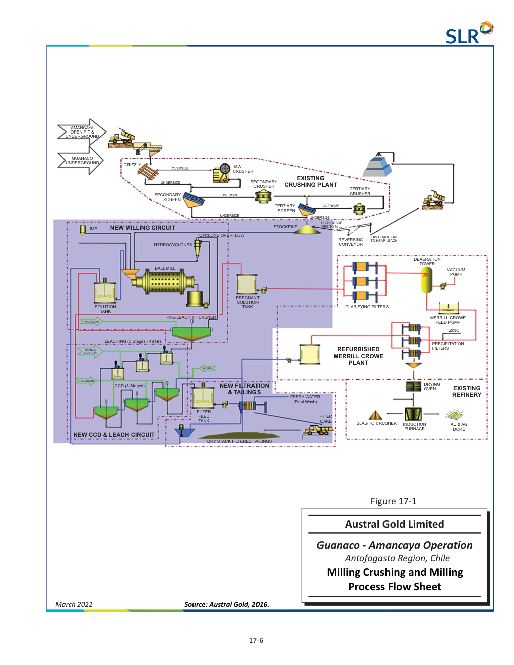
The existing three-stage crushing circuit consists of primary jaw crushing, secondary cone crushing and screening, and tertiary cone crushing and screening. Ore is trucked from the mines and dumped into a coarse ore storage bin with a grizzly positioned to prevent oversize rocks larger than 750 mm from entering. A rock breaker is available to reduce large rocks. Ore is transferred from the bin to a grizzly screen using an apron feeder. Fine material bypasses the jaw crusher while coarse material larger than 150 mm feeds the jaw crusher for primary crushing. Discharge from the jaw crusher and grizzly screen undersize is conveyed to a secondary double deck vibrating screen, with oversize feeding two secondary standard cone crushers. Discharge from secondary crushers and tertiary crusher feeds two tertiary screens, with oversize fed to two tertiary short head cone crushers. Undersize from secondary and tertiary screens is the final product. Lime is added to the conveyor feeding the truck load out bin.
The heap leach pad is designed in strips stacked to a height of three metres. After ore is dumped by trucks, it is leveled using a dozer. Irrigation drip tubes apply barren solution to the ore. Solution percolates through the pad and is collected in pipes, flowing by gravity to the pregnant solution pond. From the pond, pregnant solution is pumped to the adsorption, desorption, regeneration (ADR) plant.
The ADR plant has a design capacity of approximately 400 m³/h. The adsorption circuit consists of one train of five carbon-in-column (CIC) columns. Solution flows by gravity from column one through column five. Activated carbon is advanced counter-currently to solution flow. In the desorption circuit, carbon is first acid washed, then moved to a carbon elution column. The desorption circuit consists of two circuits operating in parallel: one designed to treat two tonnes of carbon and the second designed to treat one tonne of carbon. After elution, activated carbon is regenerated in a gas-fired carbon regeneration kiln and returned to the CIC circuit.
The elution circuit is a split Anglo American Research Laboratory (AARL) circuit. Hot caustic cyanide solution strips precious metals from the activated carbon. Eluate from the first half of the elution cycle is collected in the electrolyte tank, while solution from the second half is collected in the eluate mix tank for use in the first half of the next elution cycle. Solution from the electrolyte tank is pumped to the electrowinning (EW) circuit, where three EW cells operate in parallel. Precious metal is removed by plating onto steel wool cathodes. Sludge is dried, mixed with fluxes, and smelted in an induction furnace to produce doré bars.
Current milling operation
With the acquisition and initiation of mining at Amancaya, a milling and agitated cyanide leaching circuit was constructed at Guanaco, beginning operation in 2017. Crushed ore is delivered to the milling circuit from the existing three-stage crushing circuit. Crushed material discharges onto a reversible conveyor which feeds both the heap leach truck loading bin and the covered crushed ore stockpile at the mill.
The plant is designed to process 1,500 tpd. From the covered stockpile, two vibrating feeders draw ore from the bottom and place it on conveyors feeding the ball mill. The grinding circuit includes a single stage ball mill operating in closed circuit with hydrocyclones. Crushed ore is conveyed to the ball mill feed bin and mixed with water. Slurry discharges through a trommel screen and flows by gravity into a pump box, from which it is pumped to the cyclone cluster. Cyclone underflow returns to the ball mill, while cyclone overflow is the final product with a target grind size of P 80 150 µm.
Slurry from cyclone overflow feeds the pre-leach thickener. Underflow from the thickener, designed to produce a slurry density of 50% solids by weight, is pumped to the agitated leaching circuit. The grinding solution contains cyanide, so gold and silver dissolution begins in the grinding circuit. The leach circuit consists of three leach tanks designed to provide 48 hours of residence time. Slurry discharges from the third leach tank to the counter current decantation (CCD) washing circuit.
In the CCD circuit, leach residue advances from CCD thickener one to two and then to three. Barren solution from the Merrill-Crowe circuit is used as wash water, flowing counter current to the slurry flow. Underflow from CCD three is pumped to the filter feed tank. Two plate and frame pressure filters wash and dewater tailings to produce a filter cake containing less than 20% moisture by weight.
The existing Merrill-Crowe circuit was refurbished to accommodate ore with higher silver concentrations from Amancaya. Pregnant solution is pumped through clarifying filters and on to the de-aeration tower, a packed column operated under vacuum to remove oxygen. Zinc dust is added to the clarified, de-aerated solution where gold and silver ions are reduced to form solid metal precipitate. Solids are removed with plate and frame filter presses. Dewatered precipitate is dried, mixed with fluxes, and smelted in the existing refinery.
Washed, dewatered tailings drop by gravity into a concrete lined containment area. A front end loader places tailings into haul trucks for transport to the dry tailings storage facility (TSF). Tailings contain residual cyanide that undergoes natural degradation due to ultraviolet exposure and the dry, windy climate. Tailings are spread and plowed to assist the cyanide degradation process.
Proposed heap reprocessing project
GCM discontinued loading of the heap leach pads in 2017 and subsequently directed all ore to the mill. Ore from Guanaco was processed through February 2020. Amancaya ore is currently the primary source for mill production. Solution application on the heaps continued until operations were uneconomic, after which the ore was rinsed with water to remove residual cyanide and gold.
GCM plans to reprocess the existing heaps (Heap I, Heap II, and Heap III) by excavating the material, crushing it through a quaternary HPGR crushing circuit, and placing the crushed material on a new heap leach pad, Heap IV. A fourth stage HPGR crushing circuit will be integrated into the existing 300 tph three-stage crushing plant, which currently produces a P 80 5.3 mm product, to produce a final product of P 80 3.3 mm. The HPGR circuit design project is currently in the design and permitting stages. The HPGR circuit is in the basic engineering stage pending equipment purchases required for detailed engineering. Heap IV is in the detailed engineering stage and the required information for the permitting process is being provided.
The HPGR requires a nominal F 80 of 5.6 mm. When processing Heap III, the material can be fed directly to the HPGR circuit. When processing Heaps I and II, the material will require secondary crushing prior to the HPGR. The HPGR circuit consists of a feed hopper, screen feed conveyor, double deck screen, screen oversize conveyor feeding the HPGR, and screen undersize conveyor conveying undersized material and HPGR crushed material to the existing truck loadout conveyor.
Key reported parameters
| Parameter | Value | Basis |
|---|---|---|
| Crushing plant capacity | 300 tph | Existing three-stage circuit |
| Final product current crush size | P 80 5.3 mm | Existing crushing circuit |
| Final product proposed crush size | P 80 3.3 mm | Proposed HPGR circuit |
| HPGR nominal feed size required | F 80 5.6 mm | Design specification |
| ADR plant design capacity | 400 m³/h | Design |
| Heap leach pad lift height | 3 m | Design |
| Mill design throughput | 1,500 tpd | Design |
| Target grind size | P 80 150 µm | Design |
| Leach circuit residence time | 48 hr | Design |
| Pre-leach thickener underflow density | 50% solids by weight | Design |
| Filter cake moisture content | <20% moisture by weight | Design |
Project website: https://australgold.com/projects/operations/chile-guanaco-amancaya-mine-complex/
Technical qualifications
The HPGR circuit design project is currently in the design and permitting stages. The HPGR circuit is in the basic engineering stage pending equipment purchases required for detailed engineering. Heap IV is in the detailed engineering stage and the required information for the permitting process is being provided.
GCM discontinued loading of the heap leach pads in 2017 and subsequently directed all ore to the mill. Ore from Guanaco was processed through February 2020. Amancaya ore is currently the primary source for mill production.
An intermediate pond is available for use as part of a solution enrichment system but has never been used.
—
Source: Guanaco-Amancaya Operation , 2022 Technical Report, Section 17.0 Recovery Methods, dated March 25, 2022.
