

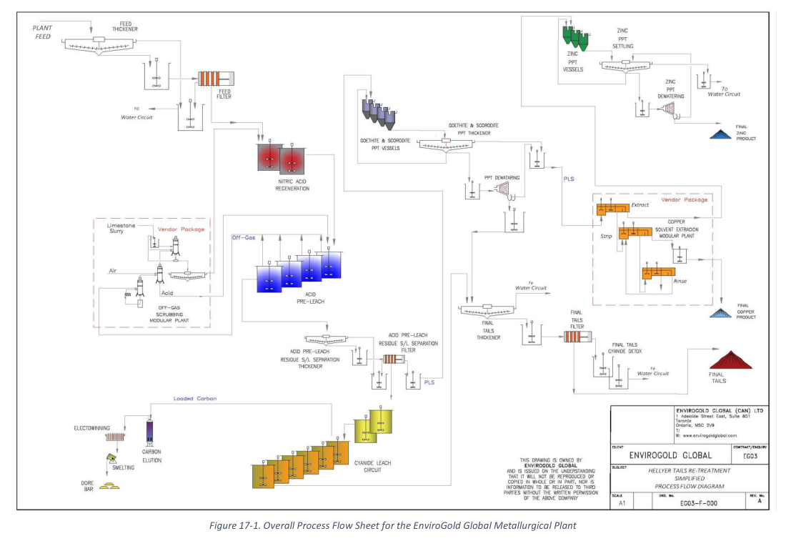
This report describes a proposed two-stage hydrometallurgical plant to reprocess zinc scavenger tailings from the Hellyer gold mine operations in Tasmania, with design criteria derived from laboratory and pilot-scale testwork.
Report context
This September 2022 NI 43-101 technical report covers the Hellyer Tailings Project, for which EnviroGold Global plans to re-process tailings from former and current lead/zinc flotation operations at the Hellyer site. The report documents a process flowsheet, design criteria, and a nine-year processing schedule, with the initial stage targeting current Hellyer Gold Mines (HGM) zinc scavenger tailings (ZST) as feed to a hydrometallurgical processing plant.
Processing route
The proposed NVRO operations are to be undertaken in two stages. Stage 1 is designed to treat 500 tonnes per day, and Stage 2 is an expansion to 3,500 tonnes per day. The same flowsheet applies to both stages. The processing plant is designed to operate 24 hours per day, 365 days per year at a nominal throughput rate of 156 tonnes per hour (dry) and 93.5% availability for the full operation.
Feed dewatering and thickening
Primary feed enters the pre-leach thickener as a slurry at 40% w/w solids and is thickened to 60% w/w solids underflow using flocculant. The underflow is pumped to an agitated holding tank and then to a filter press. Filtrate and thickener overflow are reclaimed as process make-up water. Filter cake feeds into the nitric acid regeneration and gypsum precipitation circuit.
Nitric acid regeneration and gypsum precipitation
Filter cake from feed dewatering is repulped with recycled wash water containing calcium nitrate to achieve a 40% w/w slurry. Nitric acid is regenerated by adding calcium nitrate, sulfuric acid, and water, producing gypsum and nitric acid. The reaction occurs in a tank fed by repulped slurry together with water from scrubbing of nitrogen oxides. Sulfuric acid sources are from the nitric acid leach and a fresh concentrated sulfuric acid make-up stream.
Nitric acid pre-leach
Slurry from the nitric acid regeneration area, mainly containing gypsum and pyrite, is fed to a series of agitated tanks at 21% w/w solids. Nitric acid reacts with pyrite to form aqueous ferric sulfate, ferric nitrate, and sulfuric acid, with nitric oxide produced in both gaseous and aqueous forms. Arsenopyrite, chalcopyrite, and sphalerite also react with nitric acid. Reactions are highly exothermic. Each agitated tank produces nitric oxides that are combined and transported to the gas scrubbing area.
Acid pre-leach solid-liquid separation
Slurry from the nitric acid pre-leach enters the acid pre-leach residue thickener at 8% w/w solids, with discharge temperature below 90 degrees Celsius. Thickener underflow at 45% w/w solids is pumped to an agitated holding tank prior to filtration, then to a filter press where it is washed to remove excess nitric acid. Filtrate is stored and distributed to the nitric acid regeneration circuit and the goethite and scorodite precipitation circuit.
Gas scrubbing
Gaseous streams from the nitric acid leach area containing a mixture of NO and water enter a heat exchanger at approximately 90 degrees Celsius and are cooled to 45 degrees Celsius. Cooled NO gas enters a water scrubbing unit where most NO₂ reacts with water to produce nitric acid and NO. Off-gas from water scrubbing, mainly NO and oxygen, enters a gas scrubbing unit where remaining NO is oxidised to NO₂ using limestone slurry at 20% w/w solids to produce calcium nitrate and carbon dioxide. The calcium nitrate solution is used in the nitric acid regeneration area.
Goethite and scorodite precipitation
Filtrate (pregnant leach solution) from the nitric acid leach enters a series of tanks where reactions produce a goethite and scorodite precipitate together with sulfuric and nitric acid. Limestone slurry at 40% w/w solids reacts with nitric acid and sulfuric acid to produce calcium nitrate and calcium sulfate. The precipitation product enters a thickener at 31% w/w solids; underflow exits at 50% w/w solids. The underflow is filtered and washed, and filtrate is distributed to nitric acid regeneration and copper removal areas.
Copper recovery by solvent extraction
Copper is removed from the filtrate after goethite and scorodite precipitation through ion exchange. The pregnant leach solution containing copper nitrate enters the extraction stage where copper attaches to an organic compound (ketoxime-based or aldoxime solvent extraction reagent such as LIX 984N and Acorga M5910 or similar). The loaded organic is scrubbed with dilute sulfuric acid to remove impurities, and copper is stripped with concentrated sulfuric acid.
Zinc precipitation
The solution stripped of copper enters agitated tanks where pH is elevated to precipitate aqueous zinc sulfate and zinc nitrate as basic zinc sulfate and zinc hydroxide solids. Residual copper sulfate hydrolyses to produce copper hydroxide solids and sulfuric acid. Nitric and sulfuric acids produced are neutralised with lime dosed at 30% w/w solids to produce calcium nitrate and calcium sulfate. The precipitate is mainly composed of zinc hydroxide (72.6% w/w) and gypsum (27.4% w/w) with an expected zinc grade of 47.5% based on the METSIM model.
Cyanidation leach – CIP and elution
Gold and silver recovery occurs in a conventional CIP plant. Cyanide leaching and CIP occur in two separate stages consisting of a series of agitated tanks. Residue slurry from the acid pre-leach, rinsed of residual acid, is fed into the first of two cyanide leach tanks where cyanide solution is added together with lime for pH control, and water to maintain feed density of 43% w/w solids. Air maintains dissolved oxygen levels above 6 ppm. Leached slurry flows to six agitated CIP tanks with total retention time of 15 hours, for a combined total residence time of 24 hours. Gold and silver are recovered from loaded carbon by acid wash, pressure stripping, electrowinning, and smelting to produce gold doré bars.
Tailings thickening and filtering
Tailings from the CIL/CIP process enter the tailings thickener at 43% w/w solids. Thickener underflow at 65% w/w solids is washed and filtered. Initial filtrate is stored in a cyanide-process water pond for re-use; wash water is processed for cyanide detoxification using hydrogen peroxide and copper sulfate in agitated tanks. Filtered tailings are pumped as thickened paste to the tailings storage facility.
Key reported parameters
| Parameter | Unit | Stage 1 Nominal Value | Stage 2 Expansion Nominal Value | Basis |
|---|---|---|---|---|
| General | ||||
| Annual tonnage processed | tpa | 182,500 | 1,277,500 | Design |
| Processing feed rate | tpd | 500 | 3,500 | Design |
| Processing feed rate | tph | 8 | 156 | Design |
| Plant availability | % | 93.5 | 93.5 | Design |
| Feed slurry density | % w/w | 40 | 40 | Design |
| Feed grade | ||||
| Gold | g/t | 2.44 | 2.44 | Design |
| Silver | g/t | 64.40 | 64.40 | Design |
| Copper | % | 0.13 | 0.13 | Design |
| Zinc | % | 1.41 | 1.41 | Design |
| Overall recovery | ||||
| Gold | % | 72.8 | 72.8 | Design |
| Silver | % | 87.3 | 87.3 | Design |
| Copper | % | 84.8 | 84.8 | Design |
| Zinc | % | 83.0 | 83.0 | Design |
| Acid pre-leach recovery | ||||
| Gold | % | 93.1 | 93.1 | Design |
| Silver | % | 97.3 | 97.3 | Design |
| Copper | % | 89.2 | 89.2 | Design |
| Zinc | % | 87.4 | 87.4 | Design |
| Metal recovery circuit | ||||
| Copper recovery | % | 95.0 | 95.0 | Design |
| Zinc recovery | % | 95.0 | 95.0 | Design |
| Gold recovery | % | 78.19 | 75.0 | Design |
| Silver recovery | % | 89.72 | 90.0 | Design |
Project website: https://envirogoldglobal.com/envirogold-announces-positive-pilot-plant-results-confirming-efficacy-of-metals-recovery-technology/
Note: The processing schedule shows constant feed grade across all nine years for gold (2.44 g/t), silver (64.40 g/t), copper (0.13%), and zinc (1.41%). Total tonnes processed over nine years is 9,000 kt.
Technical qualifications
The process design criteria were compiled from metallurgical test work and the METSIM model, supplemented by typical industry values, equipment supplier recommendations, and values from similar projects or other NVRO experience. The report notes that as the project advances, many assumed values will be confirmed by specific test work or further design work. A specific process design criteria for Stage 1 has not been produced, as the criteria developed for Stage 2 is considered mostly applicable to Stage 1.
The report identifies that EnviroGold Global carried out numerous leach tests in its own laboratory and over 20 acid pre-leach tests at Core Metallurgy Pty Ltd in Brisbane, Australia. Two preferred pathways to precious metal extraction were identified: a Base Case (acid pre-leach and metal recovery on whole slurry feed) and a Secondary Case (flotation pre-concentration followed by acid pre-leach). The Base Case was selected for pilot plant testing due to higher gold and silver extraction.
The report states that future additional metallurgical tests will be conducted aimed at optimizing the process diagram and reagent consumption.
—
*Source: NI 43-101 Technical Report, Hellyer Tailings Project, EnviroGold Global, September 2022. Relevant sections: 1.14 Recovery Methods, 17 Recovery Methods, 17.3 Process Design Criteria, 17.4 Processing Schedule.*
