

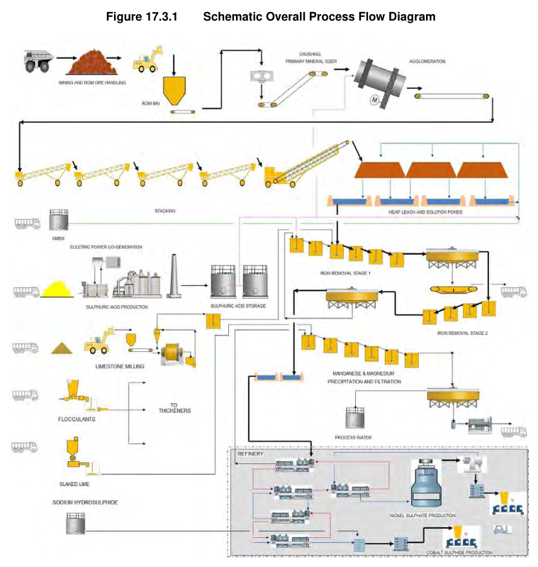
The Nico Young Project PEA describes a 3 Mtpa heap leach and solution processing operation with nickel and cobalt recovery via solvent extraction and refinery circuits.
Report context
This National Instrument 43-101 Technical Report for the Nico Young Project PEA was prepared for the project study and issued in April 2019. The processing section describes a proposed crushing, agglomeration, stacking, heap leaching and solution processing facility with associated acid plant and power generation infrastructure. The study considered ore feed at 3 Mtpa and included evaluation of individual ore types during the study period as testwork results became available.
Processing route
Ore Types and Feed
The process plant design is based on three ore types: Limonite, Saprolite and Serpentinite. The design criteria were initially developed using a blended composite ore; however, column leaching testwork demonstrated differing extraction and acid consumption for each ore type. The study therefore generated mass balance and operating cost data for each ore type individually.
The process plant consists of major sections with different planned operating schedules: crushing, agglomeration and stacking; heap leaching; solution processing; products refinery; acid plant and power station; and residue storage facility (RSF).
Crushing
Run-of-mine ore is delivered to a ROM ore storage pad and loaded into the ROM bin. Due to the expected sticky nature of the ore, no grizzly is installed over the receival hopper and no screens are included in the circuit. A single tooth rolled sizer delivers P100 50 mm sized ore to the agglomeration circuit. The sizer is fitted with scrolls capable of rejecting oversize material to an oversize bunker.
Agglomeration and Stacking
Crushed ore is conveyed to an agglomeration drum with two minutes residence time. The drum is double lined, with the inner liner left partially loose to shake off sticky ore. Sulphuric acid and process water (raffinate) are added as agglomerating agents.
A spillage tank collects slurried spillage and doses it at a controlled rate into the agglomeration drum. Agglomerates are conveyed to the stacker via a fixed tripper conveyor, grasshopper conveyors and a bandwagon conveyor to the radial stacker at the heap leach facility. The radial stacker, fitted with a stinger conveyor, stacks over a width of 75 m to a height of 4 m, using layers to limit segregation. As each heap is stacked, the irrigation network is progressively installed and irrigation commenced after a curing stage to keep agglomerates moist.
Heap Leach Facility
The heap leach system operates in modules progressing through a fixed time interval of approximately 30 days per step. Two construction and operation options were evaluated: an On-Off option and a Stacked option. Evaluation of life-of-mine costs indicated the On-Off option would provide the best economic outcome and was adopted for the study.
The On-Off option has a single pad with 15 leach cells, three vee-drains and associated ponds. The pad is sloped both longitudinally and transversely to ensure liquor drains to the correct outflow pipe. A synthetic HDPE liner is installed over the base of the leach pad cells to recover leachate and minimise migration of contaminants.
Irrigation headers run along the length of the leach pad with offtakes to each heap module. Three headers are fed from leach solution ponds with a fourth fed from the flush water pond. Individual in-line mixers are provided for each heap module to vary acid addition rate for heaps at different stages of leaching.
The stacked option comprises a Stage 1 pad with 15 leach cells and three vee-drains, supplemented with three additional pads (Stages 2, 3 and 4) each with 15 cells. A second 4 m lift comprising Stages 5 to 8 is constructed over the first lift, a third 4 m lift comprising Stages 9 to 12 over Stages 5 to 8, and a final 4 m lift comprising Stages 13 to 16 over Stages 9 to 12.
Leaching
The heap leach circuit operates with a number of stages. Agglomerated ore is stacked into heaps and leached with acidified solution in a number of stages. Raffinate is acidified and sent to Heap Leach Stage 3 via irrigation. Drainage from Stage 3 is collected in the ILS 1 Pond, re-acidified and sent to Stage 2. Drainage from Stage 2 is collected in the ILS 2 Pond, re-acidified and sent to Stage 1. Drainage from Stage 1 is collected in the PLS Pond. The spent heap from Stage 3 is washed with fresh water to retrieve residual product.
One module is under reclaim at any time. This heap also allows for drain down time prior to reclamation. One module position is vacant, preceding the stacking position, to allow safe access to the top of the heap during stacking for irrigation piping installation and maintenance.
The leach pad includes a collection pond cascade with the PLS pond at top and stormwater pond at bottom. Rain events can cause overflow from solution ponds to the stormwater pond. Solution is drawn from the stormwater pond to the barren liquor pond, with some entering the process and the rest used for the rinse module. A small amount of nickel is lost to the leach residue via this pathway; however, this has not been allowed for in the current balance.
Residue Storage Facility
The RSF is constructed using borrow materials from within the impoundment area. Initial construction includes a lined internal footprint and a containment embankment, with a HDPE synthetic liner to reduce migration of contaminants. Embankment construction uses compacted clayey materials sourced from within the impoundment. Future embankment raises are by downstream construction using borrow materials from the impoundment area. Contour drains divert rainfall runoff to adjacent valleys.
Supernatant water is recovered by pumping or decanting from the supernatant pond on the tailings surface, with collected water returned to the process plant for reuse.
Recycle Leach
The Recycle Leach step consists of two agitated tanks. Recycled slurries from Iron Removal Stage 2 thickener underflow and MHP Stage 2 thickener underflow are treated with a portion of the PLS, utilising residual sulphuric acid to redissolve precipitated nickel and cobalt before entering Iron Removal Stage 1. The recycle leach operates at 30°C with two hours total residence time.
Iron Removal
Iron Removal Stage 1 precipitates iron and aluminium at 70°C in a train of six stirred reactors. Limestone neutralises excess acidity and precipitates gypsum, ferric hydroxide and aluminium hydroxide. The incoming PLS is contacted with steam and enters the first tank. Limestone slurry is dosed into the first three tanks to incrementally raise pH down the train, which is expected to produce a more crystalline precipitate and improve dewatering properties. Final pH is expected to be about 3.5, dictated by residual iron concentration and nickel losses.
The reaction with limestone forms carbon dioxide, so tanks have 2 m freeboard. Tanks are covered to reduce heat losses and protect operators from acidic and nickel bearing aerosols. Each tank is fitted with a vent discharging clear of operator head height.
Provision is made to recycle 300% of new feed from the thickened tank discharge to the tank feed. Overall residence time is four hours in six tanks. Iron Removal Stage 1 discharge reports to a high rate thickener, thickened to 45% w/w underflow density. The underflow is separated by vacuum belt filtration, requiring at least three stages of washing for greater than 80% wash efficiency. Filter wash water pH is controlled to minimise re-dissolution of the iron precipitate.
Iron Removal Stage 2 removes further iron and aluminium by raising pH to 4.5 with limestone slurry at 62°C. The precipitated slurry is thickened in a high rate thickener to 45% w/w solids, with underflow recycled to recycle leach ahead of Iron Removal Stage 1.
Product Refinery
The products refinery is included at concept/scoping level only and is not commercially demonstrated on the feed stream that would be processed at Nico Young. The flowsheet is based on technically proven unit operations, but the integrated refinery carries technical and economic risk. No laboratory testwork has been performed for the refinery step to develop process design criteria, prepare flowsheets or perform equipment sizing at the time of the report.
The refinery is designed as follows. Neutralised PLS from Iron Removal Stage 2 is treated in solvent extraction using Versatic 10 extractant. The stripped organic used in extraction is pre-loaded with magnesium via magnesia. Raffinate from this step undergoes a Versatic recovery stage, then flows to manganese precipitation and then magnesium precipitation before being returned to the heap leach circuit.
The loaded organic is washed using dilute nickel weak electrolyte, then stripped using spent nickel electrolyte from the nickel crystallisation circuit. The stripped organic reports back to the magnesium preload circuit, while the nickel advance electrolyte enters a Cyanex 272 solvent extraction circuit to remove co-extracted metals, predominantly cobalt and zinc. Raffinate from this stage reports to the nickel crystallisation circuit, treated in a cooling crystalliser to produce a slurry of nickel sulphate crystals. Crystals are separated from mother liquor in a centrifuge, filtered, dried and packaged as high purity nickel sulphate product.
The loaded Cyanex 272 organic is stripped using an acidic solution returning from the cobalt sulphide precipitation circuit. Cobalt is precipitated from the strip solution with sodium hydrosulphide, filtered and packaged for sale as cobalt sulphide.
Manganese and Magnesium Removal
Raffinate from the refinery is treated in a series of six agitated, air sparged tanks with hydrated lime slurry to raise pH to 9.0 and precipitate a mixed manganese-magnesium residue. Precipitated solids are thickened in a high rate thickener to 30% w/w underflow. Thickener underflow is pumped to a filter feed tank and separated by horizontal plate and frame filtration to produce a 60% w/w solids filter cake, which is transported by truck for disposal in the RSF.
Thickener overflow reports to the process water tank. The majority of process water is recycled to the heap leach and re-acidified to become raffinate for leaching.
Reagents
Limestone is used to neutralise excess acid and precipitate iron and aluminium in the iron precipitation circuits. A stockpile capacity of 10 days is allowed. Limestone is fed by conveyor to a ball mill and hydrocyclone circuit, with a design product size of 80% passing 75 μm. Ground slurry is stored in a 1000 m³ agitated tank with 6 hours storage capacity. The circuit has 20% capacity above expected average consumption. Limestone slurry is circulated around the plant using a ring-main.
Flocculant types were not determined through testwork. Three different flocculant types are assumed, based on the requirement for acidic and alkaline slurry thickening and filtration conditioning, with three separate mixing plants provided.
SMBS (Sodium Metabisulphite) is added as a 20% solution into the ILS pumping system of the heap leach as a reductant to maximise cobalt extraction. Addition rate has been set at 2 tonnes of SMBS per tonne of cobalt leached. The system consists of a hopper with bag splitter, mixing and transfer, and storage tank with dosing pumps.
Magnesia is used as neutralising and buffering agent in the solvent extraction section. It is delivered in bulk via road trains with ISO containers (approximately 44 t per delivery). The main silo provides 15 days storage. Magnesia is reacted with sulphuric acid in the mixing tank to produce a magnesium sulphate reagent solution.
Sulphur is purchased out of Vancouver and shipped in up to 50,000 t capacity Handymax vessels, then loaded onto rail stock and trained to site using existing lines and a new rail spur. Sulphur is stockpiled at site in an uncovered low profile pile with 15,000 t capacity (10 days storage), managed by front end loader. The sulphur reclaim bin has 300 t capacity, with melting plant sized to operate 18 h/day, seven days/week.
Acid Plant and Power Station
The acid plant and power plants are a vendor package, not described in the report. The design is based on Chinese supplied technology. The acid plant is a large capacity plant by Chinese standards, and adoption for an Australian plant represents a higher commercial risk than conventional western options. Western suppliers offer plants differing in design but similar in interaction with the rest of the site.
The acid plant is designed to produce up to 4,400 tpd of acid with turndown capability to 30% of maximum production. The plant produces 210 t/h of high pressure steam, with a portion providing process steam demand and the remainder passed through a condensing turbo-generator to generate power. The turbo-generator supplies all project electrical power requirements. A supplementary diesel fired power station provides the sulphuric acid start-up (black start) power requirement of 14 MW.
The acid plant requires hydrated lime at an expected rate of 7 kg/h for neutralising acidity formed by oxidation of sulphur during storage. Dry hydrated lime is purchased for this purpose.
Sulphuric Acid Storage
Two tanks are specified holding 19,400 t of acid, providing 4 days supply at an acid consumption of 550 kg/t ore. This storage is required for short term variations in demand, controlled start-up and shut-down of the acid plant, and to avoid frequent starts and stops.
Start-Up Steam Boiler
A steam boiler with capacity of 115 tph of 3.5 Bar steam is required on an intermittent basis, at least during extended commissioning, to supply steam for process heating and for acid plant start-up after routine shutdowns. The boiler is required because it will take several months to ramp the plant to full production. The acid plant will be operated at minimum production rate during this period and may not produce sufficient steam for process heating. Once acid tanks are nearly full, the acid plant must shut down in a controlled way to avoid corrosion damage. Restart takes about 36 hours to pre-heat and commence sulphur burning.
The estimates allow for a suitable boiler package to be leased for the ramp-up phase. Beyond this phase,
Key reported parameters
| Parameter | Value | Basis |
|---|---|---|
| Steam boiler capacity | 115 tph at 3.5 bar | Design requirement |
| Acid plant start-up | Approximately 36 hours to preheat and restart | Operating requirement |
Project website: https://www.listcorp.com/asx/cob/cobalt-blue-holdings-limited/news/lgm-nico-young-update-and-cobalt-blue-mou-3258834.html
Technical qualifications
The report describes proposed design requirements and commissioning assumptions; actual operating performance is not established.
