

This report describes the proposed processing facilities and design criteria for the North Bullfrog Project as of the 2020 Preliminary Economic Assessment.
Report context
The North Bullfrog Project report is dated 2020 and presents a Preliminary Economic Assessment for the project, which is located in Nevada. The document includes processing design criteria and recovery methods based on metallurgical test work performed on mineralized material from the Yellowjacket, Sierra Blanca, Mayflower, Jolly Jane, and Savage Valley deposits.
Processing route
Heap Leach/ADR Facility
Mineralization from the Yellowjacket, Sierra Blanca, Mayflower, Jolly Jane, and Savage Valley open pits would be mined and placed onto a heap leach pad. Run of Mine (ROM) mineralized material would be mined at an average rate of approximately 44,700 tonnes per day and placed on a conventional heap leach pad in nominal 9.1 m (30 ft) lifts. Through the use of ultra-high-intensity blasting, the mineralization would be expected to have a P80 of approximately 84 mm (3.3 in).
Quicklime (CaO) would be added to the mineralized material prior to placement on the leach pad for pH control. Barren solution containing dilute sodium cyanide would be applied via drip emitters at an application rate of 6.1 L/h/m2 (0.0025 gpm/ft2). Pregnant solution would be collected in a divided pond where sediment would settle out of the solution before overflowing an internal berm. The pregnant solution pumps would feed a pair of vertical carbon-in-columns (VCIC). A second pair of VCICs would be added to manage the increased barren flow rate in Year 5. Gold and silver extracted from the pregnant solution onto activated carbon would be further processed via the desorption and recovery circuit to produce a final doré product.
The leach pad would be designed as a double-lined facility consisting of a layer of geosynthetic clay liner (GCL) having a hydraulic conductivity less than or equal to 1×10⁻⁶ centimeters per second (cm/s) which acts as the secondary liner system. A layer of 80-mil geosynthetic liner made from high density polyethylene (HDPE) would be placed over the GCL to act as the primary liner. A leak detection system would be installed between the GCL and the HDPE liner.
The mixed ROM mineralization and gravity mill tails would be stacked in lifts averaging 9.1 m (30 ft) high to a maximum of 91.4 m (300 ft) at a nominal rate of 47,315 tonnes per day. The leach pad would be constructed in four phases. Phase 1A would have an area of approximately 630k m2 with a capacity to hold 38.5M tonnes. Phase 1B would have an area of approximately 342k m2 with a capacity of 29.6M tonnes. Phase 2 would have a lined area of approximately 953k m2 and a capacity of 92.9M tonnes. Phase 3 expansion would include an additional 605k m2 of lined area with a capacity of 60.5M tonnes.
Dilute cyanide solution would be distributed to the leach pad by three vertical turbine pumps installed in a common barren solution sump. One pump would serve as an installed spare, with two pumps operating to deliver the barren solution at a flow rate of 949 m3/h. During Phase 2 leach pad construction, an additional barren sump and pumps would be added to deliver an additional 1,300 m3/h for a combined barren flow up to 2,249 m3/h.
The solution would be pumped through an 18-inch distribution pipeline around the toe of the leach pad. The solution would be conveyed to each consecutive lift via a series of 12-inch riser pipes. Seven risers would be installed for Phase 1A, with an additional four risers installed to service Phase 1B. Approximately seven risers would be installed for the Phase 2 leach pad expansion, with an additional seven risers for Phase 3.
Blasting, loading, hauling, and placement of the mineralized material on the leach pad would be by an owner mining fleet. The haul trucks would place mineralized material on the lift being constructed. The mineralized material would be truck stacked (end dumped) and then pushed out and cross-ripped by a dozer to eliminate any compaction that occurred during placement.
Gravity Mill Circuit
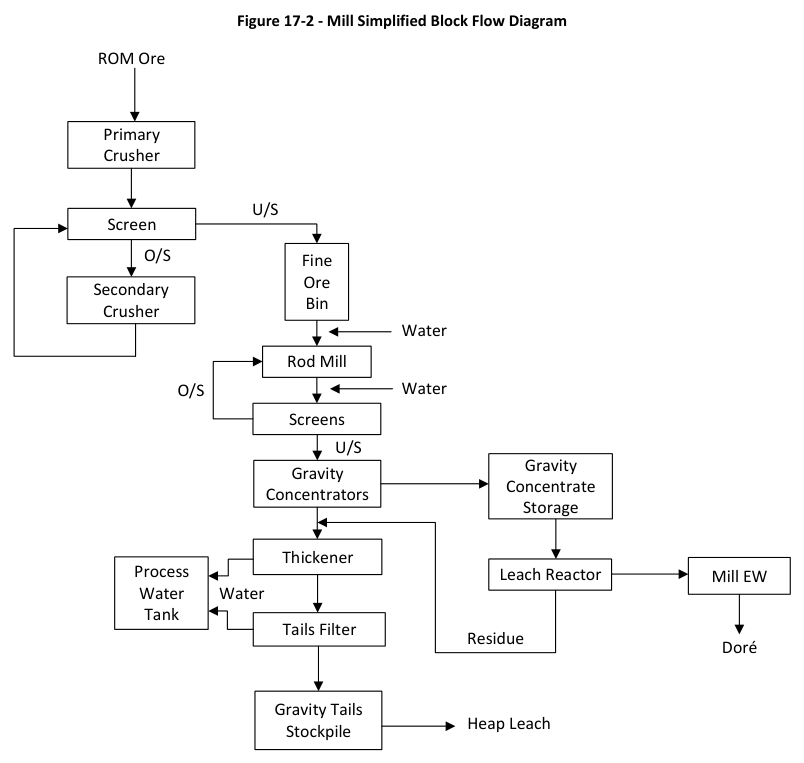
High grade vein and vein stockwork mineralization from the Yellowjacket deposit would be processed through a mill circuit at a rate of approximately 4,700 tonnes per day. The mineralized material would be run through a two-stage portable crushing circuit and conveyed into a fine crushed product bin at a P80 of 19 mm (¾ in). The fine crushed product bin would feed a rod mill with a target product size of 48 mesh. Slurry classification would be via multi-stage screens. The screen undersize would feed a gravity concentrator circuit. Gravity concentrate would be processed via an intense leach reactor with the pregnant solution processed via a dedicated electrowinning cell for doré production. The gravity tails would be thickened and filtered prior to stockpiling. The filtered tails would be loaded into haul trucks and dumped on the leach pad for residual gold and silver recovery.
Carbon Adsorption and Desorption
Pregnant solution would flow from the heap leach pad into the pregnant solution pond. The solution would then be pumped into two parallel vertical carbon-in-column (VCIC) trains at a nominal flowrate of 863 m3/h. During Phase 2, a second set of VCICs and pregnant solution pumps would be installed to accommodate the necessary increase in flow, operating at a nominal 1,181 m3/hr for a combined pregnant solution flow of 2,044 m3/hr.
Pregnant solution would enter the bottom of each VCIC at a nominal flowrate of 432 m3/hr. Six separate chambers would contain 2.7 tonnes of carbon each for gold and silver adsorption. The design efficiency would be 98.4% for gold and 87.7% for silver.
Loaded carbon would be stripped using a Pressurized ZADRA strip scheme, utilizing 10-12 bed volumes of a circulated 149°C (300°F) solution of a minimum 1.25% caustic (NaOH) and 0.2% sodium cyanide (NaCN) concentration at a minimum pressure of 380 kPa (55 psig). The strip cycle time was estimated at 10 hours per day.
Carbon regeneration would be performed in an electric rotary kiln, heating the carbon to 650 to 750 °C in a slightly oxidizing atmosphere to remove organic fouling.
Electrowinning and Refining
The heap leach electrowinning (EW) cells would be designed to treat 30 to 45 gpm per cell of pregnant strip solution in two cells operated in parallel with each cell containing 34 anodes and 33 cathodes. A dedicated 20 anode/19 cathode EW cell would receive the pregnant solution from the gravity mill intense cyanidation reactor.
The loaded cathodes would be pressure washed, producing sludge that would be pumped to a plate-and-frame filter press. After mercury removal in a retort, the dried sludge would be mixed with fluxes and smelted in an induction furnace to produce doré bullion.
Key reported parameters
| Parameter | Value | Unit | Basis |
|---|---|---|---|
| ROM mineralized material to leach pad | 44,700 | tonnes per day | Design |
| Mill throughput | 4,700 | tonnes per day | Design |
| Total mineralized material to leach pad | 47,300 | tonnes per day | Design |
| LOM mineralized material to leach pad | 221.4 | million tonnes | Design |
| P80 (heap leach) | 84 | mm | Design |
| P80 (mill feed) | 19 | mm | Design |
| Rod mill target product size | 48 | mesh | Design |
| Crusher Work Index (CWi) | 11.5 | kWh/t | Testwork |
| Design bulk density | 1.65 | t/m3 | Testwork |
| AVG ROM mineralized material grade, Au | 0.20 | gpt | Design |
| AVG ROM mineralized material grade, Ag | 0.55 | gpt | Design |
| AVG mill tails grade, Au | 0.80 | gpt | Design |
| AVG mill tails grade, Ag | 9.71 | gpt | Design |
| LOM AVG leach pad grade, Au | 0.23 | gpt | Design |
| LOM AVG leach pad grade, Ag | 1.12 | gpt | Design |
| Heap leach gold recovery – Yellowjacket | 73.2 | % | Testwork |
| Heap leach gold recovery – Sierra Blanca | 73.2 | % | Testwork |
| Heap leach gold recovery – Savage Valley | 74.1 | % | Testwork |
| Heap leach gold recovery – Jolly Jane | 61.7 | % | Testwork |
| Heap leach gold recovery – Mayflower | 76.4 | % | Testwork |
| Heap leach gold recovery – mill tails | 71.8 | % | Testwork |
| Heap leach silver recovery – Yellowjacket | 13.3 | % | Testwork |
| Heap leach silver recovery – mill tails | 59.1 | % | Testwork |
| Lift height | 9.1 | m | Design |
| Maximum heap height | 91.4 | m | Design |
| Solution application rate | 6.1 | L/h/m2 | Design |
| Design barren flow rate, Phase 1 | 949 | m3/h | Design |
| Design barren flow rate, Phases 2-3 | 2,249 | m3/h | Design |
| Average leach cycle, Phase 1 | 60 | days | Design |
| Average leach cycle, Phases 2-3 | 75 | days | Design |
| Solution cyanide concentration | 250 | mg/L | Design |
| Carbon adsorption efficiency, Au | 98.4 | % | Design |
| Carbon adsorption efficiency, Ag | 87.7 | % | Design |
| Heap/ADR cyanide consumption | 0.25 | kg/t mineralized material | Testwork |
| Heap/ADR lime consumption | 1.25 | kg/t mineralized material | Testwork |
| Strip temperature | 149 | °C | Design |
| Strip pressure | 380 | kPa | Design |
Project website: https://www.anglogoldashanti.com/portfolio/americas/united-states-projects/
Technical qualifications
This document is a Preliminary Economic Assessment as defined by National Instrument 43-101. The report states that test work has been performed on the NBP mineralized material by a number of metallurgical laboratories, as described in Section 13, which is not included in this extract. The test work has indicated that the Yellowjacket, Sierra Blanca, Mayflower, Jolly Jane, and Savage Valley mineralized materials are amenable to cyanide leaching for the recovery of gold and silver. The process design criteria and recovery estimates are based on this test work together with design assumptions. The report does not include full flowsheet details, operating data from historical production, or economic analysis within the sections provided. Recovery percentages vary by deposit and by metal, as shown in the table above.
—
Source: North Bullfrog Project , 2020 Preliminary Economic Assessment, Sections 17 (Recovery Methods, Process Design Basis, Heap Leach and ADR, Heap Leach Pad and Solution Distribution, ROM Truck Stacking, Ponds, Carbon Adsorption, Carbon Handling, Carbon Acid Washing, Carbon Stripping (Elution), Carbon Regeneration, Electrowinning, Refining, Reagents).
