

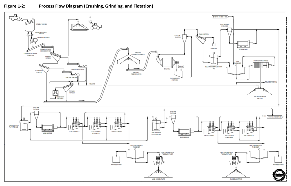
The proposed process route for the Revel Ridge Project comprises crushing, particle sorting, grinding, bulk sulphide flotation, sequential lead and zinc flotation, pressure oxidation, and gold-silver recovery via Merrill Crowe.
Report context
This technical report, dated December 29, 2023, presents a NI 43-101 Technical Report and Preliminary Economic Assessment for the Revel Ridge Project. The processing design described herein is based on previous testwork programs performed on the deposit, Ausenco’s extensive database of reference projects, and in-house modelling programs. The plant is designed for a throughput of 2,920 tonnes per day or 1.1 million tonnes per annum at 92% availability. The crushing and sorting circuit is designed with an availability of 65%. The plant will operate with two 12-hour shifts per day, 365 days per year.
Processing route
Crushing and particle sorting
Mineralized material is hauled from the mine and tipped into the grizzly run-of-mine bin and fed into the vibrating grizzly feeder. Oversized material is fed to the primary jaw crusher, while undersized material and the product from the jaw crusher are deposited onto the crusher discharge conveyor. The material is conveyed via the primary screen feed conveyor to a double deck primary screen.
The oversize material from the screen is recirculated back to the primary crusher. The midsize material is conveyed to the coarse particle sorter and the undersize material is conveyed to a single deck secondary screen. The oversize material from the secondary screen passes through the fine particle sorter and the undersize is conveyed to the stockpile. The particle sorting uses x-ray transmission to separate low density rejects from high density product. The rejects from both particle sorters are high in limestone, which will be used for neutralizing acid created in the pressure oxidation circuit. The products are fed to the tertiary screen where the oversize feeds the secondary crusher, which is in a closed circuit, and the fines are conveyed to the stockpile.
Grinding and classification
Reclaim feeders move the material onto a feed conveyor which transfers the material to the ball mill with added water. The ball mill product is discharged through a trommel and the oversize is screened out and discharged to a scats bunker, whereas the trommel undersize is discharged into the cyclone feed pumpbox. Water is added to the cyclone feed pumpbox to obtain the appropriate density prior to pumping to the cyclone. The cyclone overflow is advanced to the flotation circuit.
Flotation plant
Bulk flotation. The bulk flotation consists of rougher flotation cells and a concentrate regrind circuit. The overflow from the cyclone cluster reports to the rougher cell feed box. Frother and collector reagents are added to the feed box. The concentrate from the rougher flotation is collected via launders and pumped to a cluster of regrind cyclones, while the tailings from each flotation cell moves into the next cell. The final tailings from the rougher flotation train are pumped to a tailings thickener. Fine material in the cyclone overflow bypasses the regrind mill, while coarse material reporting to the underflow is reground by a mill with the product collected along with the cyclone overflow and pumped to the lead flotation process.
Lead rougher flotation. The slurry entering the lead flotation is conditioned in two agitated conditioning tanks set in parallel. The tanks feed into a single train of five lead rougher flotation cells in series. The rougher concentrate is pumped into a cluster of cyclones. The underflow from the cyclones is reground in a mill, and the product is pumped into the lead cleaner flotation process with the cyclone overflow. The lead cleaner flotation process consists of a lead cleaner, a lead cleaner-scavenger and a second lead cleaner in series. The tailings from first lead cleaner moves into the cleaner-scavenger, while the concentrate is collected via a launder. The concentrate from the lead cleaner-scavenger is pumped to the second lead cleaner, while the cleaner-scavenger tailings are collected with the tailings from the lead rougher cells to be pumped into the zinc flotation. The second lead cleaner concentrate is collected with the concentrate from the first lead cleaner and fed into the lead concentrate thickener. The thickened underflow is pumped into a dedicated lead concentrate filter.
Zinc rougher flotation. The tailings from the lead rougher cells and the lead cleaner scavenger cell are pumped to two agitated conditioning tanks in parallel. The tanks feed into a single train series of three zinc rougher flotation cells. The concentrate from the zinc rougher flotation is pumped into a cluster of cyclones. The underflow from the cyclones is reground in a mill; the product is pumped into the zinc cleaner flotation process with the cyclone overflow. The zinc cleaner flotation process consists of a zinc cleaner, zinc cleaner-scavenger, and second zinc cleaner in series. The second zinc cleaner concentrate collects with the concentrate from the first zinc cleaner and feeds into the zinc concentrate thickener. The thickened underflow is pumped into a dedicated zinc concentrate filter.
Pressure oxidation
The tailings from the zinc rougher flotation and the zinc cleaner-scavenger are treated in a five-chambered autoclave. The autoclave is fed with oxygen for an oxygen partial pressure of 690 kPa(g) and a total pressure of 3,150 kPa(a) and operated at 220 degrees C to oxidize the sulphide minerals in order to liberate the gold and silver. After oxidation, the slurry exits the autoclave through a choke value into a flash tank where the pressure and temperature of the mixture is reduced by flashing water to steam to ambient pressure. The slurry then moves into a series of four hot cure tanks; the slurry is thickened and washed in a series of counter-current decantation thickeners to remove the acidic solution from the solids. The solution from the CCD train transfers into a train of six agitated solution neutralization tanks, which then feeds the solution neutralization thickener and the solids fed to the final tailings thickener. The thickened oxidized solids from the CCD train pass through the lime boil heater, three lime boil tanks, a slurry cooling tank and then a regrind mill. The regrind mill reduces the final particle size of the solids in the slurry to a target P80 size of 15 micrometres.
Cyanide leaching and Merrill Crowe
The re-ground material moves into a series of leach tanks for leaching with sodium cyanide and lime slurry to control the pH. The leach slurry is filtered and washed on belt filters to recover the gold-silver bearing solution. The pregnant leach solution collects in a tank and passes through a series of two clarifier filters and a deaeration tower. The solution then moves into the Merrill Crowe circuit. Zinc dust and lead nitrate are added to the solution to precipitate gold and silver. The resulting sludge is filtered to remove moisture, and the filtrate is transferred to the barren solution tank.
Gold recovery
The dry sludge is moved to a standard gold-recovery process consisting of two mercury retort ovens, flux mixer and feeder, barring furnace, and pouring table where gold dore is produced as a final saleable product.
Cyanide detoxification and tailings handling
The filtered leach solids are repulped and fed into a cyanide detox tank with copper sulphate, sodium metabisulphite, lime slurry, and low-pressure air. The slurry is treated to destroy any residual cyanide before being fed to a paste plant to be mixed with cement and used for mine backfill.
Key reported parameters
| Parameter | Units | Value | Basis |
|---|---|---|---|
| Annual Throughput | Mt/a | 1.1 | Design |
| Daily Throughput | t/d | 2,920 | Design |
| ROM Head Grade, Pb – design | % | 1.75 | Design |
| ROM Head Grade, Zn – design | % | 3.26 | Design |
| ROM Head Grade, Au – design | g/t | 4.28 | Design |
| ROM Head Grade, Ag – design | g/t | 41.5 | Design |
| Crushing and Sorting Availability | % | 65 | Design |
| Grinding and Flotation Availability | % | 92 | Design |
| Concentrate Filtration Availability | % | 75 | Design |
| POX and Au Plant Availability | % | 92 | Design |
| Crushing Plant Capacity, for design | t/h | 187 | Design |
| ROM Feed Size, F100 | mm | 500 | Design |
| Bond Crushing Work Index | kWh/t | 11.9 | Testwork |
| Primary Crushing product size, P80 | mm | 74 | Design |
| Secondary crushing product size, F80 | mm | 14.6 | Design |
| Number of Particle Sorters | # | 1 coarse and 1 fine sorter | Design |
| Particle Sorter Rejects | % | 35 | Design |
| Limestone content in Sorter Rejects | % | 80 | Design |
| Grinding Plant Capacity, design | t/h | 100 | Design |
| JK Drop Weight (Axb) value | – | 59 | Testwork |
| Bond Ball Mill Work Index, design | kWh/t | 9.7 | Testwork |
| Grinding Feed Size, F100 | mm | 10 | Design |
| Grinding Product Size, P80 | um | 150 | Design |
| Ball Mill Specific Energy | kWh/t | 8.81 | Design |
| Bulk Flotation Rougher Residence time, design | min | 24 | Design |
| Bulk Regrind Circuit Product Size, P80 | um | 20 | Design |
| Lead Flotation Rougher Residence time, design | min | 5 | Design |
| Lead Regrind Circuit Product Size, P80 | um | 10 | Design |
| Lead Cleaner Flotation Residence time, design | min | 5 | Design |
| Lead Scavenger Flotation Residence time, design | min | 5 | Design |
| Zinc Flotation Rougher Residence time, design | min | 12 | Design |
| Zinc Regrind Circuit Product Size, P80 | um | 8 | Design |
| Zinc Cleaner Flotation Residence time, design | min | 5 | Design |
| Zinc Scavenger Flotation Residence time, design | min | 5 | Design |
| Pressure Oxidation Operating Temperature | degrees C | 220 | Design |
| Pressure Oxidation Operating Oxygen Over Pressure | kPa | 690 | Design |
| Pressure Oxidation Retention Time | min | 60 | Design |
| Pressure Oxidation Operating Pressure | kPa | 3,150 | Design |
| Leach Regrind Circuit Product Size, P80 | um | 15 | Design |
| Leach Residence Time | h | 24 | Design |
| Leach extraction, Au | % | 96 | Design |
| Leach extraction, Ag | % | 80 | Design |
| Merrill Crowe Retention Time | h | 8 | Design |
| Precious Metal (Au + Ag) production, design | kg/d | 60 | Design |
| Cyanide Detox WAD Cyanide target, design | mg/L | 1 | Design |
| Total Process Plant Installed Power (without Oxygen Facility) | MW | 16.9 | Design |
| Oxygen Facility Installed Power | MW | 10.0 | Design |
Project website: https://goldsilver.ai/mining-projects/revel-ridge
Technical qualifications
The process design criteria are based on previous testwork programs performed on the deposit, Ausenco’s extensive database of reference projects, and in-house modelling programs. The process design criteria table (Table 17-1) presents design values for throughput, head grades, and equipment parameters. The Bond Crushing Work Index of 11.9 kWh/t and JK Drop Weight (Axb) value of 59 are testwork-derived parameters. The Bond Ball Mill Work Index of 9.7 kWh/t is listed as a design value based on testwork. Leach extraction values of 96% for gold and 80% for silver are design assumptions rather than demonstrated performance. This report presents a preliminary economic assessment; no historical operating data from a Revel Ridge mine or processing plant are included in the report.
Source: NI 43-101 Technical Report and Preliminary Economic Assessment, Revel Ridge Project, December 29, 2023, Section 17 Recovery Methods.
