

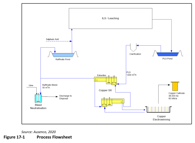
This technical report describes the proposed processing route for pregnant leach solution from in-situ copper recovery to produce LME grade copper cathode via solvent extraction and electrowinning.
Report context
The Van Dyke Copper Project 2020 Technical Report presents a process design for a copper recovery plant that will receive pregnant leach solution (PLS) from an In-situ Copper Recovery (ISCR) leaching operation. The proposed plant will process between 580 to 3,900 m³/h of PLS, averaging 2,800 m³/h, and produce 38,555 t/year (85 Mlb/year) as LME grade copper cathode. The processing facility design is based on conventional solvent extraction and electrowinning equipment, with design criteria derived from industry typical standards, as no downstream testwork had been completed at the time of the report.
Processing route
Proposed Process Flowsheet
The processing plant will receive PLS from the ISCR leaching operation. Preliminary metallurgical test work was used to select the recovery method for the project. The design criteria for the process facility were based on industry typical standards, with the report noting that copper solvent extraction and electrowinning are well established commercial processes and the process design is based on conventional equipment used in these applications.
The main processing areas will include copper solvent extraction (SX), copper electrowinning (EW), bleed solution neutralisation, and reagents and services.
Copper Solvent Extraction (SX)
PLS solution received from the ILS operation will be stored in a PLS pond with 24-hour residence time, providing a buffer between ILS and SX and allowing some suspended solids to settle. The PLS will be pumped from the pond to two dynamic bed clarifiers operating in parallel to reduce suspended solids further and mitigate crud formation risk in the SX. Flocculant and coagulant will be added to assist with solids settling. The clarifiers will produce an overflow PLS containing less than 50 ppm suspended solids.
The PLS flowrate is anticipated to range from 580 to 3,900 m³/h, with copper grade ranging between 0.4 to 4.2 g/L over the life of the mine. The average PLS flowrate is 2,800 m³/h.
The SX circuit will consist of two extract stages and a single strip stage. Based on expected iron and manganese concentrations in the PLS, a wash stage should not be required. In the extraction stages, copper in the PLS is loaded onto the extractant in the organic phase, generating sulphuric acid according to the reaction: CuSO₄ + H₂-Organic = Cu-Organic + H₂SO₄.
The aqueous stream exiting the second extraction settler is termed raffinate and will contain approximately 110 ppm copper and 7.8 g/L sulphuric acid. Raffinate will pass through an after settler to recover entrained organic before being pumped to a raffinate pond with 24-hour residence time, providing surge capacity between SX and ILS. Raffinate will be returned to the ILS operation where additional sulphuric acid will be added before use in the leaching process.
Spent electrolyte from the copper electrowinning process will be used to strip copper from loaded organic back into the aqueous phase. The spent electrolyte will have a high sulphuric acid concentration (180 g/L), reversing the extraction reaction by consuming sulphuric acid and producing copper sulphate. The resulting advance electrolyte (rich electrolyte) will have a target copper concentration of 50 g/L and will be returned to electrowinning.
Crud handling will be a batch operation conducted when required. Crud will be removed from settlers via a dedicated removal system. Diluent will be added to aid phase separation, and crud will be processed in a centrifuge. Solids waste will be collected in drums while centrate will be returned to the first extraction stage mixing tank. Clay treatment will be provided for organic, where clay is added to the crud tank and mixed before being pumped to a clay filter.
Copper Electrowinning (EW)
Rich electrolyte from the filter feed tank will be pumped through co-matrix filters containing anthracite, sand, garnet, and coalescing media to remove entrained organic and solids. The filtered stream will be pumped to an electrolyte inter-exchanger where temperature is increased by spent electrolyte returning to SX. The strong electrolyte will continue to a trimming heat exchanger for heating on start-up or cooling during normal operation, then to an electrolyte circulation tank where it will be mixed with recirculating spent electrolyte.
In the EW plant, copper-rich electrolyte will be circulated through electrowinning cells containing a series of anode and cathode plates. The electrolyte will be subjected to direct current, and copper ions will migrate from solution to the cathode and be electrochemically reduced to form elemental copper sheets. The copper EW tank house will consist of 82 cells, each containing 84 cathodes and 85 anodes. Nominal copper cathode production will be 38,555 t/y, with the tankhouse capable of producing 40,000 t/y at maximum capacity.
Most solution exiting the cells will be mixed with rich electrolyte and returned as feed. A portion of the exiting solution will be used as spent electrolyte and pumped to the electrolyte inter-exchanger and then to the SX strip circuit. The spent electrolyte will be split, with the majority sent to SX strip and a small flow diverted to the SX extract circuit as a bleed to prevent impurity build-up.
Cathode plates will be periodically removed from cells using six-day growth cycles, washed, and stripped of copper deposits in a fully automatic stripping machine. The resulting LME grade ‘A’ copper sheets (>99.99% copper) will be the final product.
Bleed Solution Neutralisation
A small flow of process solution will be bled from the system to remove excess water and prevent build-up of deleterious elements. The bleed stream will be pumped to neutralisation tanks where pH will be increased to 7 by lime slurry addition. The lime will neutralise acid and precipitate soluble metals. Neutralisation of sulphuric acid forms gypsum precipitate, while precipitated metals will be in hydroxide form. The neutralised bleed solution will be pumped to a lined cell for disposal.
Key reported parameters
| Description | Unit | Value | Basis |
|---|---|---|---|
| PLS flowrate (design) | m³/h | 1,200 | Design criterion |
| PLS copper grade | g/L | 3.9 | Design criterion |
| PLS flowrate range | m³/h | 580 – 3,900 | Anticipated life-of-mine |
| Average PLS flowrate | m³/h | 2,800 | Anticipated average |
| PLS copper grade range | g/L | 0.4 – 4.2 | Anticipated life-of-mine |
| PLS pond storage capacity | h | 24 | Design criterion |
| PLS pond volume | m³ | 28,800 | Design criterion |
| Copper extraction | % | 97.1 | Design criterion |
| Spent electrolyte copper | g/L | 37 | Design criterion |
| Rich electrolyte copper | g/L | 50 | Design criterion |
| Cathode production rate | t/a | 38,555 | Nominal design |
| Cathode production design | t/a | 40,000 | Maximum capacity |
| Number of EW cells | 82 | Design criterion | |
| Cathodes per cell | 84 | Design criterion | |
| Anodes per cell | 85 | Design criterion | |
| Current density – nominal | A/m² | 320 | Design criterion |
| Cell voltage – nominal | V | 2.1 | Design criterion |
| Current efficiency | % | 90 | Design criterion |
| Plating cycle | days | 6 | Design criterion |
| Electrolyte sulphuric acid | g/L | 180 | Design criterion |
| Bleed solution volume | m³/h | 50 | Design criterion |
| Neutralisation target pH | 7 | Design criterion |
Project website: https://copperfoxmetals.com/projects/van-dyke/overview/
Technical qualifications
The process design criteria were generated based on industry typical parameters, as no testwork had been completed for the downstream process plant at the time of the report. The report states that the mineral processing and metallurgical testing of the ILS process to date did not identify any deleterious elements in the Van Dyke PLS that may negatively impact the performance of the SX plant and therefore copper recovery. Recommendations for future considerations for fluctuation in PLS volume and grades are addressed elsewhere in the report (Section 26). The crud formation rate is noted as being plant specific and difficult to predict.
—
Source: Van Dyke Copper Project , 2020 Technical Report, Sections 17 Recovery Methods, 17.1 Proposed Process Flowsheet, 17.2 Key Process Design Criteria, and 17.3 Process Description.
