

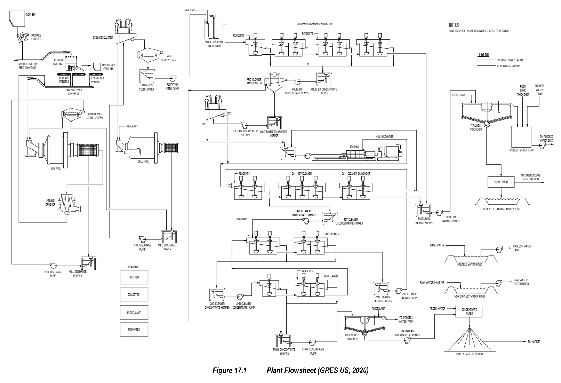
The Black Butte Copper Project in Montana is designed around a conventional flotation concentrator that will process underground sulfide ore into copper concentrate for export, with tailings converted to paste for backfill and storage.
The Black Butte Copper Project is a copper project located in Montana, with Sandfire Resources America Inc. as the issuer. The Preliminary Feasibility Study Update covers the Johnny Lee and Lowry deposits. The planned processing plant will treat underground sulfide mineralization at an annualized rate of 1.2 Mt/a, producing copper sulfide concentrate for market export. Construction timing is not stated in the supplied recovery methods material.
Critical Data
| Parameter | Value | Unit | Notes |
|---|---|---|---|
| Annual throughput | 1,204,500 | t/a | Design value |
| Feed grade Cu (LOM) | 2.9 | % | Design value |
| Concentrate Cu grade | 22.5 | % | Design value |
| Cu recovery (LOM) | 88 | % | Design value |
| Concentrate produced (LOM average) | 130,000 | t/a | Design value |
| Crushing circuit operating hours | 5,694 | hours | Design value |
| Milling circuit operating hours | 8,059 | hours | Design value |
| Crushing treatment rate | 270 | t/h | Design value |
| Milling treatment rate | 150 | t/h | Design value |
| Primary grind size P80 | 38 | µm | Design value |
| Concentrate regrind size P80 | 10-15 | µm | Design value |
| Crushing circuit availability | 70 | % | Design value |
| Grinding circuit availability | 92 | % | Design value |
| SAG mill installed motor power | 2,000 | kW | Design value |
| SAG mill power drawn | 1,440 | kW | Design value |
| Ball mill installed motor power | 5,500 | kW | Design value |
| Ball mill power drawn | 4,790 | kW | Design value |
| Specific comminution energy (total) | 35.4 | kWh/t | Design value |
| SAG mill specific energy | 9.6 | kWh/t | Design value |
| Ball mill specific energy | 25.7 | kWh/t | Design value |
| SMC A*b | 48.4 | Not applicable | Rock breakage parameter |
| SMC DWi | 6.38 | kWh/m³ | Rock breakage parameter |
| ROM bin capacity | 90 | t | Design value |
| Coarse ore bin capacity | 2,500 | t | Design value |
| Coarse ore bin surge | 16.7 | hours | Design value |
| Grinding media charge | 27 | % | Ball mill design charge |
| Ball mill critical speed | 75 | % | Operating value |
| Cyclone circulating load | 250 | % | Design value |
| Cyclone overflow pulp density | 35 | % solids | Design value |
| Flotation pulp pH | 9.5 | Not applicable | Design value |
| Combined Cu recovery (LOM average) | 87.5 | % | Design value |
| Concentrate thickened solids | 57 | % | Design value |
| Concentrate storage capacity | 300 | m³ | Design value |
| Concentrate storage time | 18 | hours | Design value |
| Target concentrate moisture | 10 | % | Test work based |
| Tailings thickener underflow density | 55-60 | % solids | Design value |
| Paste filter feed tank capacity | 300 | m³ | Design value |
| Water treatment rate | 114 | m³/h | Nominal value |
| Process water pond capacity | 100,000 | m³ | Total fill capacity |
| Combined recovery prior to regrind | 53 | % | Design value |
| Rougher/scavenger concentrate grade | 9-11 | % Cu | Design value |
| Jameson cell concentrate grade | 26.2 | % Cu | Circuit modification value |
| Direct processing workforce | 114 | employees | Includes general administration |
Overview
The selected process for recovering copper from the Johnny Lee and Lowry ores will employ industry-standard comminution and flotation technologies. Feed to the new treatment plant will consist of fresh massive sulfide underground ore. The processing plant will be a conventional flotation-based concentrator consisting of crushing, grinding, sulfide flotation, thickening, and filtering. The copper plant tails will be converted to paste for use as underground backfill or stored in a new surface cemented tailings facility. Final concentrate will be shipped off site for export.
The process plant will operate on a continuous 24 hour-a-day basis, via two 12-hour processing shifts. The design availability of the crushing and grinding circuits will be 70% and 92%, respectively. The design processing rate of 150 dry t/h will provide for the annualized treatment of underground sulfide mineralization.
When the Johnny Lee Lower Copper Zone ore is depleted, the plant will process ore from the Lowry deposit blended with Johnny Lee Upper Copper Zone ore with minor modifications required. The recovery of copper from the Lowry deposit is expected to be higher than from the Johnny Lee deposit. Geometallurgical testwork will confirm this expectation in the next phase of testing. The water requirements for processing Lowry ore are assumed to be the same as for the Johnny Lee ore, though preliminary testwork indicates that Lowry ore will not require the fine grind the Johnny Lee ore will need, therefore requiring less water.
Key Process Stages
The crushing circuit was designed by Orway Mineral Consultants based on an Impact Crush Work index of 10.7 kWh/t. A single stage crushing circuit has been selected to complement the selection of a SAG mill as the primary grinding method. Underground ore will be delivered to the Run of Mine pad and stored in separate stockpile fingers according to ore type and grade to facilitate blending. Stockpiled material will be reclaimed by a Front-End Loader for direct feed to the crushing plant ROM bin. Ore will be withdrawn from the 90 t capacity ROM bin using a variable speed apron feeder which will discharge onto a 1.12 m wide by 6.16 m vibrating grizzly with 64 mm bar spacing. Based on the selected ROM size distribution, 67% of the ROM feed will report to the jaw crusher, while the grizzly undersize will bypass the crusher via a chute directly onto the crushed ore conveyor. A single toggle jaw crusher (CJ411) has been selected for the crushing duty. The jaw crusher Closed Side Setting will be maintained at 100 mm to achieve a crushed product size P80 of 99 mm. Crushed rock will be conveyed to a Coarse Ore Bin of 2,500 t capacity that will provide 16.7 hours of surge.
A two stage SAG and ball mill grinding circuit has been selected to achieve the target grind size P80 of 38 µm to the flotation circuit. The mill selection has been based on the OMC simulation and an SMC specific energy calculation to determine the grinding power requirements and mill sizes. Fresh ore will be reclaimed from the Coarse Ore Bin by two variable speed feeders and discharged onto the fixed speed mill feed conveyor. The primary SAG mill, with dimensions 6.10 m diameter by 3.05 m Effective Grinding Length, will be equipped with a 2,000 kW variable speed mill motor. A grate discharge system using 25 mm grates has been selected in combination with a discharge trommel at 12 mm apertures. Oversize from the SAG mill trommel will be conveyed to a pebble crusher for size reduction of the pebbles prior to returning to the mill feed conveyor. Trommel undersize pulp will be pumped to a primary sizing screen fitted with 2 mm polyurethane screen panels. Screen oversize will be treated in closed circuit with the SAG mill while undersize material will gravitate to the ball mill discharge sump. The nominal SAG mill transfer size to the secondary ball mill will be 600 µm and controlled by the primary sizing screen.
The secondary ball mill will be a fixed speed grate discharge mill measuring 5.50 m in diameter by 8.10 m Effective Grinding Length, operating at 75% of critical speed with a design ball charge of 27%. A grate discharge system using 15 mm grates will provide slurry flow to the mill trommel screen, fitted with 10 mm aperture panels. The trommel screen is required to remove ball scats only. The OMC simulations highlighted the importance of minimizing the SAG mill transfer top size to the secondary ball mill. A vibrating screen has been installed to classify the SAG mill discharge product with a sizing screen fitted with 2 mm screen decks to control the transfer size to the ball mill circuit.
The secondary ball mill will operate in closed circuit with a cluster of 250 mm diameter cyclones. The cyclones have been designed with a circulating load of 250% and will have an overflow pulp density of 35% solids to achieve the flotation feed size P80 of 38 µm. The cyclone overflow will report to a horizontal, vibrating trash screen 1.5 m wide by 4.8 m long. The trash screen will be fitted with polyurethane screen panels having an aperture of 1.0 mm. Cyclone underflow will be directed to the ball mill feed chute. Trash screen oversize will gravitate directly to a trash bin. Undersize from the trash screen will gravitate to the copper flotation feed conditioning tank. A launder sampler will be located on the trash screen underflow and the sample will be pumped to the On-Stream Analyzer for elemental and density analysis.
The copper minerals, chalcopyrite and tennantite, will be recovered from the pyrite and non-sulfide gangue throughout the copper flotation circuit at an elevated pulp pH of 9.5. Lime will be used to maintain the flotation circuit pH conditions. Aero 3477 will be the main copper sulfide collector and will be added in a stage-wise manner to avoid overdosing, which may result in the inadvertent recovery of the pyrite to the copper concentrate. Depressants, sodium monophosphate and dextrin, will be used to minimize the flotation of the pyrite and carbonaceous gangue material. Depressants for the rougher/scavenger flotation circuit will be added in the grinding circuit. Depressants will also be added into the concentrate regrind circuit to maximize the rejection of pyrite in the cleaner flotation circuit.
The copper rougher/scavenger circuit will consist of three rougher 30 m³ tank cells and four 30 m³ scavenger tank cells. Rougher/scavenger concentrate at 9% to 11% Cu will be pumped to the Jameson re-cleaner flash cell, an E2532/6 rectangular J-cell. The circuit has been modified to produce a final grade concentrate of 26.2% Cu and improve the overall recovery by effectively recovering 53% of the copper prior to the regrind stage. J-cell tails will be directed to the regrind circuit, 150 mm diameter dewatering cyclones to enable control of the feed density from the cyclone underflow to the regrind mill. Cyclone underflow will gravitate to a regrind mill feed hopper for further size reduction by a self-classifying M5000 IsaMill. The regrind feed cyclone overflow will be combined with the regrind mill discharge and pumped to the 10 m³ pre-cleaner conditioning tank.
Copper cleaning will be conducted in three stages. The first stage will be an open circuit first cleaner and cleaner scavenger. The second and third cleaners will operate in closed circuit. The first cleaner flotation stage will consist of five conventional 16 m³ cleaner cells followed by two 16 m³ cleaner scavenger cells. The concentrate from the first copper cleaner cells will be pumped to the second copper cleaner cells for further upgrading, while the concentrate from the cleaner scavenger cells will be recirculated to the rougher/scavenger regrind circuit after the cyclones. The tailings from the cleaner scavenger cells will be pumped via the OSA to the final tailings feed box. The second cleaning stage will consist of four 8 m³ conventional cells. The tailings from the second cleaner stage will discharge directly into the first cell of the first cleaner flotation stage. The second cleaner concentrate will be pumped to the third cleaning stage which will consist of three 4.3 m³ flotation cells. Tailings from the third cleaner stage will be directed to the second cleaner flotation stage. Concentrate from the final copper cleaning stage will be combined with the Jameson cell concentrate to produce the final concentrate of 22.5% Cu with a combined recovery of 87.5% Cu on a life of mine average. The final copper concentrate will be pumped via the OSA to the copper concentrate thickener feed hopper.
A six-stream Courier analyzer system will be installed in the flotation circuit to provide continuous online analysis. Slurry samples from nominated streams will be directed to the Courier for multi-element analysis. Analytical results from the Courier will be displayed and recorded on a monitor in the plant control room and shift composite sub samples will be collected for metallurgical accounting purposes. The streams that will be measured online include flotation feed, copper rougher/scavenger concentrate, copper scavenger tail, copper cleaner scavenger tail, copper final concentrate, and Jameson flash cell concentrate.
Additional Interesting Data and Summary
The final copper concentrate slurry, the filtrate from the copper filter, and the spillage from the copper concentrate area will be pumped to the feedwell of the copper concentrate thickener. A 12 m diameter high-rate copper concentrate thickener fitted with an auto-dilution feed system has been selected for the project. Flocculant will be mixed into the feed slurry to increase the solids settling rate and control the clarity of the thickener overflow. The copper concentrate slurry will be thickened to 57% solids and will then be pumped to a 300 m³ agitated concentrate storage tank by one of two peristaltic type pumps in a duty and standby configuration. The copper concentrate thickener overflow will be pumped to the tailings thickener overflow tank.
The copper concentrate storage tank will have capacity to store up to 18 hours of copper concentrate production. A single duty filter feed pump will pump the copper concentrate to a Lorax type PF plate and frame type pressure filter which has been selected due to the fine particle size distribution of the concentrate. A narrow chamber depth of 33 mm has been used for sizing based on the test work results to realize the target concentrate moisture content of 10%. A PF60-60 has been selected for the required duty. The filter will operate automatically via a dedicated vendor supplied programmable logic controller and operator interface system linked to the plant control system. The filter filtrate will be pumped to the concentrate thickener. The filter cake will discharge onto the floor of the concentrate storage shed from where it will be loaded into sealable containers by front end loader on loadout trucks while parked on a weighbridge. The trucks will then transport the concentrate either directly to port or to a rail head for transfer to rail and port transport options. Containers will be unloaded or stored on a hard stand at the port awaiting shipment in bulk carriers.
The final tailings, consisting of the copper scavenger tails and the copper cleaner scavenger tails, will be dewatered in an 18 m diameter high-rate thickener. Additional streams from the water treatment plant, the paste plant, and decant water from the Cemented Tailings Facility will also feed the thickener. Flocculant will be added to increase the settling rate and underflow density to between 55% and 60% solids. Thickened tailings will then be pumped to the paste plant filter feed tank. Thickener overflow will gravitate to a tailings thickener overflow tank, which also collects the overflow from the copper thickener. Water from the tank will be used as process water within the circuit and will be supplemented by process water from the process water dam.
Thickened plant tailings from the tailings thickener will be pumped to a 300 m³ capacity paste filter feed tank. Variable speed filter feed pumps will transfer the material at a feed density of 55% to 60% solids to two horizontal plate and frame filters. The design has allowed for 85% of the thickened tailings to be fed to the filters, with the remaining 15% of the underflow being recombined at the paste mixer to generate the paste and avoid the requirements of additional water dilution.
Treatment of the underground sulfide ore by flotation will require a specific suite of reagents. These reagents include activators to enhance the flotation response of selected minerals, depressants to suppress gangue minerals, frothers to promote froth formation and stability, and collectors to selectively recover the target minerals. The copper collector will be a dithiophosphate with the trade name Aero 3477, supplied as a 100% concentrated solution in 1,000 L bulk boxes. The frother will be Methyl Isobutyl Carbinol, also supplied as a 100% concentrated solution in 1,000 L bulk boxes. Sodium Monophosphate is a modifying and depressant agent to stop the activation of iron sulfide minerals from free lead and copper ions. It will be supplied in powder form in 1,000 kg bulk bags. Sodium Monophosphate mixing will be completed manually by the operator. Lime will be used to increase the pH of process streams and neutralize the acidic condition of the stream, and to form hydroxides of particular metals. The lime will be supplied as hydrated lime in bulk as a powder. Upon receipt at site, it will be pneumatically transferred into an 80 t capacity silo. The hydrated lime will be mixed with raw water in a lime mixing tank to produce a 20% slurry. Dextrins are water soluble polysaccharides and are used as depressants for carbonaceous pyrite. Dextrin mixing will be completed automatically in a mixing system similar to that of flocculant, generating a 10% solution. This solution will be transferred to a storage tank for distribution to the primary SAG mill and concentrate regrind mill circuits. Antiscalant will be added to the suction side of both process water pumps to inhibit the formation of scale in the process water system.
The flocculant will be an anionic flocculant with a trade name Magnafloc 10, supplied as a powder in 800 kg bulk bags. The flocculant mixing system will be a proprietary packaged plant consisting of a dry flocculant hopper, powder feed and wetting system, mixing tank, transfer pump and storage tank. Flocculant will be mixed automatically with raw water on a batch basis to generate a 0.25% solution. Ground blast furnace slag, a semi cementitious material, will be used in the paste plant as the binder to the underground stopes and the Cemented Tailings Facility. Portland type I and II cement will be used in the paste plant as the cement for the underground stopes and the Cemented Tailings Facility paste requirements. Both binders are added on a ratio to dry tonnes of mine backfill and mixed in a paste mixer prior to being pumped to the desired location.
Operators will monitor and run the plant from PC-based Human-Machine Interface systems located in the process plant control room. Operations will be monitored and controlled via PC-based Supervisory Control and Data Acquisition screens using Citect software. The ability to remotely start and stop plant equipment from the operator screens via start and stop sequences or by manually starting or stopping individual equipment will be provided. Motor starters, main isolators and distribution board feeders will be located in the Motor Control Centers. Each MCC will contain a PLC which, with the SCADA system, will make up the Process Control System. The PCS will provide the interface between the drives and instrumentation and the operators. Hardwired outputs and inputs for plant equipment and field devices will be interfaced through these PLCs in which plant start-up and shutdown sequences and interlocks will be programmed. All equipment will be equipped with local start and stop buttons. There will be two modes of operation for each piece of equipment: local and remote.
Underground dewatering water at a nominal rate of 114 m³/h will be treated in a proprietary reverse osmosis Water Treatment Plant located at the processing plant site. Treated water will be to RO quality and will be used in part as water for the process plant with the bulk of the water returned to an underground infiltration gallery system. Raw water will be a combination of returned water from the process water pond and the water treatment plant, following the clarification and filter stage. It will then be stored in the new raw water tank at the plant site. Raw water will be used for process water makeup, reagent mixing, flocculant dilution, cloth washing in filtration, gland water, regrind milling cooling water, and fire water. Two raw water distribution pumps arranged in a duty and standby configuration will be located at the raw water tank. The lower portion of the raw water tank will provide a dedicated fire water reservoir for the fire water system. The fire water system will include two pumps: an electric fire water pump and a diesel driven fire water pump.
Process water will be primarily recovered from the process plant as thickener overflow streams to the tailings thickener overflow tank. Two dedicated process water pumps will then supply the water around the circuit. Inflow from the water treatment plant and makeup water from the Process Water Pond will provide the additional makeup for operations. The Process Water Pond has a total fill capacity of 100,000 m³ and will be used to store process water as the main storage facility. Potable water will be provided from the Water Treatment Plant after the RO skid treatment system discharge and pumped to a potable water tank. A UV sterilization system will be included for the potable water discharge from the tank.
Compressed air will be supplied by two dedicated plant air compressors along with a standby unit for any high demands and redundancy in the system. Instrument air will be provided from the plant air system via an air dryer and filter. An independent air system will be used for the paste plant filter snap air system. Flotation air to the flotation circuits will be supplied by two dedicated blowers arranged in a duty and standby configuration.
The operating philosophy of the processing plant has been based on a continuous 24-hour operation with two 12-hour shift rotations. The shift rotations will use a 7 days on and 7 days off, 4 panel shift roster to achieve the production targets. Technical based personnel will be on a 9 days on and 5 days off roster with a back-to-back arrangement for supervisors and superintendent roles. Senior management and administration will be based on a 5 days on and 2 days off arrangement. The total direct workforce requirement for process plant operation and general administration is 114 employees.
Key Processes
- Single stage jaw crushing with grizzly bypass, producing P80 of 99 mm
- Two stage SAG and ball mill grinding to P80 of 38 µm
- Copper rougher and scavenger flotation in tank cells
- Jameson cell flash cleaning prior to regrind
- IsaMill regrind to P80 of 10-15 µm
- Three stages of conventional cleaner flotation
- Concentrate thickening and pressure filtration to 10% moisture
- Tailings thickening with paste backfill plant for underground and surface storage
- On-stream analysis via six-stream Courier system
- Reagent preparation and distribution including collector, frother, depressants, flocculant, and binders
Source: Black Butte Copper Project Preliminary Feasibility Study Update, July 28, 2026. Project website: Black Butte Copper Project
Technical report and processing history
The following archived source profiles have been consolidated here to preserve the project’s processing history and study context.
Black Butte Copper Project — Feasibility Study Technical Report NI 43-101
Black Butte Copper Project — Feasibility Study Technical Report NI 43-101
| Company | Sandfire Resources America Inc. |
| Date | 2024 |
| Region | Montana, USA |
| Commodities | Copper |
| Mine Type | Underground |
| Status | Development |
Executive Summary
This Feasibility Study Technical Report outlines the recovery methods and infrastructure for the Black Butte Copper Project. The selected process recovery method utilizes industry-standard comminution and flotation technologies to produce a copper sulphide concentrate for market export. The design processing rate is 150 dry tph, providing for the annualized treatment of 1.2 Mtpa of UG sulphide mineralization, producing approximately 120 ktpa of copper sulphide concentrate. The process plant will operate continuously on a 24-hour basis.
The processing circuit includes a primary jaw crusher feeding a two-stage SAG and ball mill grinding circuit. The grinding circuit produces a cyclone overflow product at a target 80% passing size of 38 microns for feed to the flotation circuit. The flotation circuit consists of Cu rougher and scavenger stages, followed by a concentrate regrind circuit and four stages of Cu cleaning, including a Jameson flotation cell. Final concentrate is dewatered using a thickener and pressure filter.
Tailings management involves dewatering in a conventional tailings thickener, with thickened tailings pumped to a paste plant for the generation of cemented paste for mine backfill or storage in a Cemented Tailings Facility (CTF). The project infrastructure includes water treatment, power supply, and support facilities designed to support the underground mining operation and processing plant.
Processing Profile
Reports
Website: https://blackbuttecopper.com/
Report Date: 2024
Region: Montana, USA
Project Status: Development
Commodity: Copper
Throughput:
Mine Life:
Mine Type: Underground
Ore type:
Black Butte Copper Project — 2019 Technical Report
Black Butte Copper Project — 2019 Technical Report
| Company | SRA |
| Date | 2019 |
| Region | Alaska, USA |
| Commodities | Copper |
Executive Summary
This section of the NI 43-101 Technical Report outlines the recovery methods developed for the Black Butte Copper Project. A metallurgical test program was utilized to establish a process flow-sheet designed to produce a saleable copper concentrate. The proposed recovery process includes crushing, grinding to 38 µm K 80, rougher flotation, regrinding of the rougher concentrate to 10 µm K 80, a three-stage cleaner flotation circuit, and filtering of the concentrate.
The report notes that previous results from a preliminary economic assessment (PEA) disclosed in July 2013 by Tintina Resources (the precursor to SRA) are now considered obsolete. The Black Butte Copper Project is no longer classified at a PEA level. SRA is currently progressing the project through additional studies related to mining, milling, processing, and economics, though these studies are not yet complete for disclosure at the time of this report.
This technical report was prepared by SRK Consulting (U.S.), Inc. for SRA. It serves as an update to the Mineral Resource evaluation, replacing the 2013 Mineral Resource evaluation which is now considered obsolete.
Reports
Website: https://www.srk.com/en/projects/mineral-resource-estimation-black-butte-copper-project
Report Date: 2019
Region: Alaska, USA
Project Status:
Commodity: Copper
Throughput:
Mine Life:
Mine Type:
Ore type:
Black Butte Copper Project — 2012 Technical Report
Black Butte Copper Project — 2012 Technical Report
| Company | Resource Modeling Inc. / Arthur H. Winckers & Associates |
| Date | 2012-01-13 |
| Region | Meagher County, Montana |
| Commodities | Copper |
| Status | Development |
Executive Summary
This technical report section outlines the proposed recovery methods for the Black Butte Copper Project. The metallurgical testing indicates that copper minerals will be recovered through a conventional flotation circuit following primary grinding. The process design is based on locked cycle test results, ensuring the flowsheet and process conditions are optimized for the specific ore characteristics of the project.
The flotation circuit is designed to utilize a rougher stage followed by three stages of cleaning. This configuration aims to maximize copper recovery while managing concentrate grade. The locked cycle test conditions, detailed in the associated tables and figures within the full report, provide the basis for the proposed processing parameters. No leaching or alternative recovery methods are currently proposed in this section of the report.
Processing Profile
Reports
- entities/BlackButteCopperProject
Website: https://www.globenewswire.com/news-release/2013/07/24/1359719/0/en/Tintina-Files-Updated-Technical-Report-and-Preliminary-Economic-Assessment-for-its-Black-Butte-Copper-Project-Montana-USA.html
Report Date: 2012-01-13
Region: Meagher County, Montana
Project Status: Development
Commodity: Copper
Throughput:
Mine Life:
Mine Type:
Ore type:
Black Butte Copper Project — Pre-Feasibility Study
Black Butte Copper Project — Pre-Feasibility Study
| Company | Sandfire Resources America Inc. |
| Date | Pre-Feasibility Study |
| Region | Montana |
| Commodities | Copper |
| Mine Type | Underground |
| Throughput | 150 t/h |
| Annual Production | 129,000 t/a concentrate |
| Status | Pre-Feasibility Study |
Executive Summary
The Black Butte Copper Project Pre-Feasibility Study outlines the processing of underground sulphide mineralization via a conventional comminution and flotation circuit. The design processing rate is 150 dry t/h, treating 1.2 Mt/a of ore to produce approximately 129,000 t/a of copper sulphide concentrate. The plant operates continuously on a 24-hour basis with two 12-hour shifts.
The recovery method involves primary jaw crushing followed by a two-stage SAG and ball mill grinding circuit to achieve a P80 of 38 microns. Copper recovery is achieved through rougher, scavenger, and cleaner flotation stages, utilizing Jameson cells for flash cleaning and IsaMills for regrind. Final concentrate is thickened and pressure filtered for export, while tailings are processed into paste for underground backfill or storage in a Cemented Tailings Facility.
The project infrastructure includes a dedicated water treatment plant, power supply, and surface facilities to support the underground mining operations. Reagents such as Aero 3477, MIBC, and lime are utilized to optimize flotation performance and pH control. The overall design aims for a Life of Mine average copper recovery of 85.8%.
Website: https://sandfireamerica.com/document/sandfire-resources-america-files-black-butte-copper-project-technical-report/
Report Date: Pre-Feasibility Study
Region: Montana
Project Status: Pre-Feasibility Study
Commodity: Copper
Throughput: 150 t/h
Mine Life:
Mine Type: Underground
Ore type:
