

A review draft profile of the May 7, 2012 Preliminary Economic Assessment (PEA) for the Caballo Blanco Gold Heap Leach project in Veracruz, Mexico, re-addressed on October 31, 2016, detailing the proposed crushing, heap leach, carbon adsorption, and refining process route.
Report context
This profile is based on the Preliminary Economic Assessment (PEA) for the Caballo Blanco Gold Heap Leach project, prepared by K D Engineering and associated authors for the project owner at the time, Goldgroup Mining Inc. The report, with an effective date of May 7, 2012, was re-addressed on October 31, 2016, to Candelaria Mining Corp. following ownership changes. The re-addressed report contains no new technical information; it was reissued to support Candelaria's disclosure. The study presents a proposed, not existing, processing facility and associated infrastructure, and the following summary shows the design parameters and testwork results described within the 2012 technical report.
Processing route
Material handling and crushing
The proposed process begins with run-of-mine (ROM) material delivered from the open pit to the crushing system by 40-tonne end-dump haul trucks. The haul distance is 3.4 km over 15 m wide, two-way traffic roads, with access improved by a 1.2 km, 5.5 m wide, one-way tunnel through the mountain separating the pit from the process area.
ROM is either end-dumped directly into a dump hopper or reclaimed to it from a ROM crusher feed stockpile. A belt feeder discharges the material onto a vibrating grizzly screen fitted with 150 mm gratings. Screen oversize reports to a primary jaw crusher with a closed-side setting of 125 mm. The crushed particles are combined with the grizzly undersize to form a coarse product stream with a P80 of minus 140 mm. This product is transferred via conveyor to a coarse ore storage bin.
A secondary crushing circuit comprises an apron feeder, a transfer conveyor, and a vibrating double-deck screen. The top deck scalps particles larger than 78 mm, and the second deck removes middlings between 78 and 34 mm. Oversize material is fed to a secondary cone crusher with a closed-side setting of 34 mm. Screen undersize and secondary crusher product form a final product with a P80 of 38 mm, which reports to a product stockpile with an 8-hour surge capacity of approximately 6,700 tonnes.
Pebble lime is added to the crushed material on the conveyor between the primary and secondary crushing circuits to control pH on the leach pad. The lime feed rate is regulated by a rotary valve at the silo discharge.
Heap leach pad and solution management
Crushed material is transported from the stockpile to the leach pad by truck and end-dumped. Initial lifts are built using a truck ramp, which extends upwards as the pad progresses. The heap is constructed with 6-meter lifts, overall side slopes of 2.5H:1V with benching, and a design loading rate of 20,000 tonnes/day. Phase 1 storage capacity is 13.3 million tonnes (about 2 years of operation) with a 42-meter heap height; Phase 2 increases to 36.0 million tonnes (approximately 6 years of operation) and an ultimate height of 84 meters. The cycle time is 60 days.
The heap is divided into two phases and nine conceptual leaching cells. A proposed liner system, detailed on MWH Drawing 4 (Appendix 7), consists of (bottom to top): 300 mm of compacted clay liner, an 80-mil HDPE or LLDPE geomembrane (to be determined at a later design stage), a 250-mil geonet leachate collection and recovery system (LCRS) layer, and a 600 mm over liner with a maximum particle size of approximately 37 mm. The clay liner provides a secondary barrier and protects the geomembrane; the over liner protects it from coarse material during placement.
Leachate is collected at the base of the heap by a network of 100 mm diameter perforated corrugated plastic tubing (CPT) collection pipes spaced at 15-meter intervals. Permeability testing of the over liner is recommended prior to final design to refine the piping. The secondary collection pipes discharge to primary collection pipes, approximately 200 mm diameter perforated CPT or solid-wall HDPE, which gravity flow to collection ponds. Storm water from the heap is directed to an Events Pond sized for the wettest 100-year/24-hour storm event, and in-heap storage is provided for large events.
The process ponds (PLS, ILS, and BS ponds) are designed with a nominal operational volume of 10,000 m³ plus 4,417 m³ of freeboard, for a total of 14,417 m³ each. Lined with 80-mil HDPE or LLDPE, these ponds manage normal operational fluctuations and allow for solution concentration management. The Events Pond, with a capacity of 383,600 m³, collects storm water and leachate and is sized for the wettest season in the 33-year period of record, with a treatment capacity of 250 m³/hr. The process and Events Ponds use a double-liner system with an LCRS sump between liners. The Events Pond liner includes a 150 mm clay layer beneath an 80-mil HDPE or LLDPE liner.
Gold recovery and refining
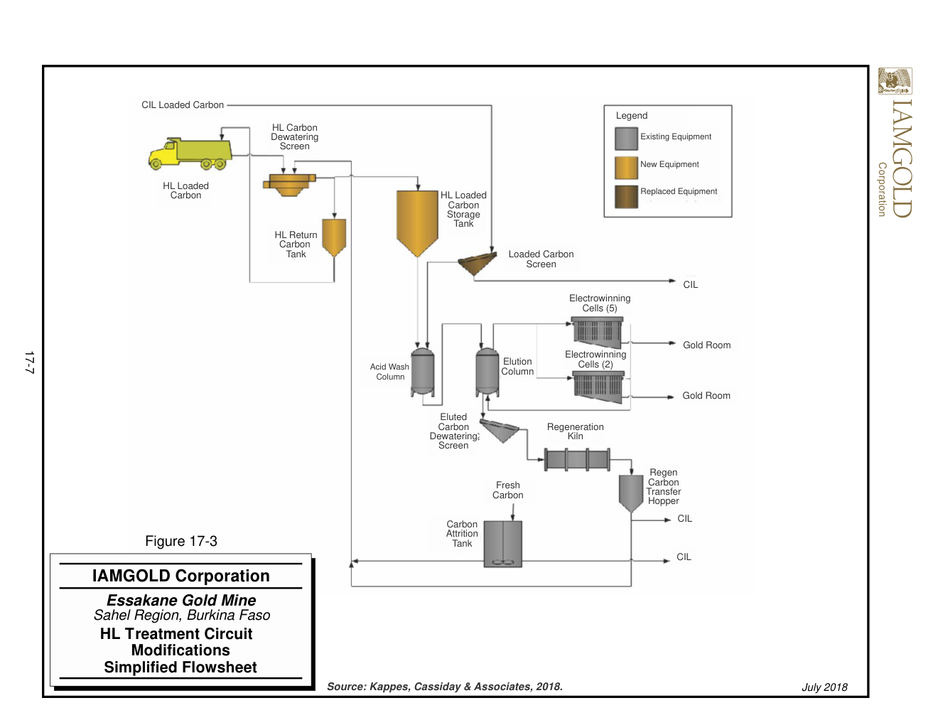
Pregnant leach solution (PLS) from the PLS pond is pumped to a series of five carbon columns where gold is adsorbed onto carbon. Barren solution from adsorption discharges across a safety screen to catch fine carbon, then flows to a barren tank for pH adjustment with slaked lime and cyanide addition before being recycled to the heap. Loaded carbon is transferred to an acid wash vessel,a weak hydrochloric acid wash removes inorganic contaminants,then to an elution vessel for a pressurized Zadra strip using hot caustic solution.
The rich electrolyte is pumped to the refinery for electrowinning. Precious metals deposit onto stainless steel wool cathodes as sludge, with an estimated 90 to 99 percent of metal recovered from the electrolyte. The sludge is filtered in a plate and frame pressure filter, dried in a retort to volatilize and recover mercury, then smelted in a furnace with fluxes. The resulting doré bars (approximately 500 ounces each) are shipped for refining. A carbon regeneration kiln operates under a reducing atmosphere to remove organic contaminants and re-activate the carbon.
Testwork and design limitations
Heap permeability testing has not been conducted to date. The report notes that truck loading compacts material and may reduce permeability, and that material decrepitation could further reduce drainage. Preliminary observations suggest relatively good drainage, but verification through laboratory testing is required at a later design stage. The heap stability has not been evaluated; static and dynamic stability analyses and strength testing of the clay sub-base are recommended.
- Preliminary subgrade investigations indicate organic topsoils (50–130 mm) over a fat clay layer (85–130 mm), underlain by a thick hard rock basalt layer estimated up to 40 meters thick.
- The events pond design assumes a water treatment capacity of 250 m³/hr, and additional studies are required to determine the level and type of in-pond treatment.
Key reported parameters
| Parameter | Value | Basis |
|---|---|---|
| Primary crusher | Jaw crusher, 125 mm closed-side setting | Proposed design |
| Secondary crusher | Cone crusher, 34 mm closed-side setting | Proposed design |
| Product size (crushed ore) | P80 = 38 mm | Proposed design |
| Coarse product size (primary) | P80 = 140 mm | Proposed design |
| Heap loading rate | 20,000 tonnes/day | Proposed design |
| Lift height | 6 meters | Proposed design |
| Heap slope (overall) | 2.5H:1V | Proposed design |
| Phase 1 storage | 13.3 million tonnes (~2 years) | Proposed design |
| Phase 2 storage | 36.0 million tonnes (~6 years) | Proposed design |
| Phase 1 heap height | 42 meters | Proposed design |
| Phase 2 heap height (ultimate) | 84 meters | Proposed design |
| Cycle time | 60 days | Proposed design |
| Leach pad cells | 9 (conceptual) | Proposed design |
| Collection pipe diameter (secondary) | 100 mm, spaced 15 m | Proposed design |
| Collection pipe diameter (primary) | 200 mm | Proposed design |
| Process pond volume (each) | 14,417 m³ (10,000 m³ operational + 4,417 m³ freeboard) | Proposed design |
| Events Pond volume | 383,600 m³ | Proposed design |
| Events Pond treatment capacity | 250 m³/hr | Design assumption |
| Liner (geomembrane) | 80 mil HDPE or LLDPE | Proposed design |
| Liner (clay layer) | 300 mm compacted clay | Proposed design |
| Over liner | 600 mm, max particle 37 mm | Proposed design |
| Gold recovery (electrowinning) | 90–99% metal removal | Electrolyte basis |
| Doré bar weight | 500 ounces | Design |
Technical qualifications
This profile describes a historical, proposed design from the May 7, 2012 PEA, re-addressed on October 31, 2016, without new technical information. The study is a preliminary economic assessment, not a feasibility study, and the processing route has not been constructed or operated. Heap permeability testing had not been conducted at the time of the report, and heap stability was not evaluated. The report recommends further geotechnical and metallurgical testing. The leach pad liner system, pond sizes, and water balance are based on preliminary design criteria and may be revised during later design stages. All information is effective as of May 7, 2012, and no claims are made that the project is currently operating or that the described facilities exist today.
Source: *Preliminary Economic Assessment Caballo Blanco Gold Heap Leach, Veracruz, Mexico*, K D Engineering, Document No. Q443-04-028, Project No. 443-04, effective May 7, 2012, re-addressed October 31, 2016, Section 17.0 Recovery Methods (pages 17-1 to 17-8).
