

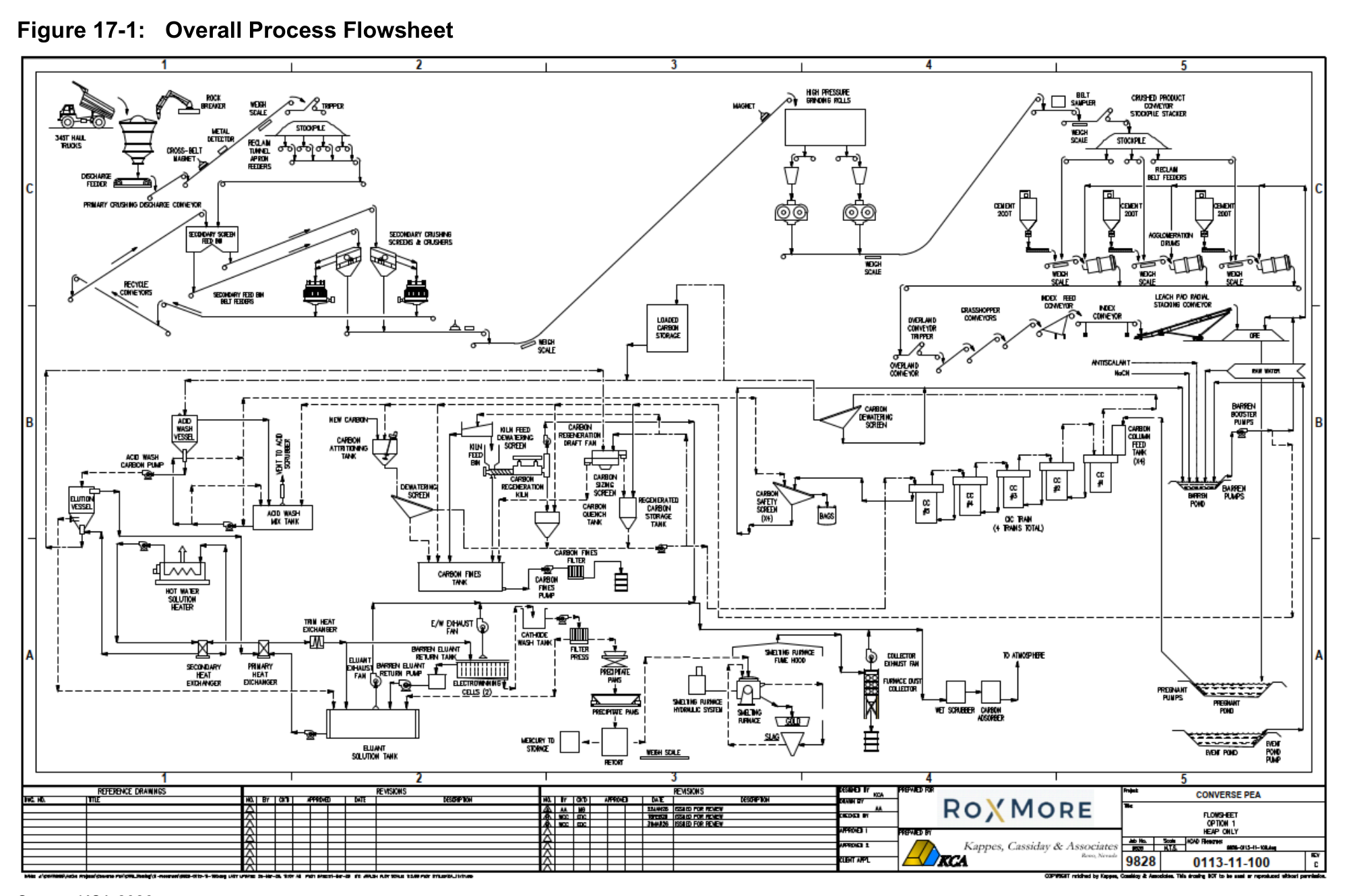
The Converse Project in Nevada is planned as a heap leach gold and silver operation with a three-stage crushing circuit, cement agglomeration, and carbon adsorption processing.
The Converse Project is an advanced exploration and development project located in Nevada, USA, owned by Roxmore Resources Inc., formerly Axcap Ventures Inc. The project targets gold and silver mineralization and is at the preliminary economic assessment stage of development. The NI 43-101 technical report was prepared by SLR Consulting (Canada) Ltd. with an effective date of May 2, 2026. Based on the minable Mineral Resource of 299.8 Mt and an established processing rate of 61,644 tpd, the project has an estimated life of 14.5 years including ramp-up. The report does not state expected construction timing for the project.
Critical Data
| Parameter | Value | Unit | Notes |
|---|---|---|---|
| Annual tonnage processed | 22.5 | Mtpa | Design value |
| Crushing production rate | 61,644 | tpd | Average |
| Crushing product size | 80% passing 6.3 | mm | Design value |
| Crusher availability | 75 | % | Design value |
| Conveyor stacking system availability | 80 | % | Design value |
| Leaching cycle | 120 | days | Based on metallurgical test work |
| LOM average gold recovery | 70.9 | % | Test result |
| LOM average sodium cyanide consumption | 0.64 | kg/t | Test result |
| LOM average cement consumption | 6 | kg/t | Design value |
| Heap lift height | 10 | m | Design value |
| Quantity of lifts | 8 | unitless | Design value |
| Maximum stacking height | 80 | m | Design value |
| LOM heap capacity | 310 | Mt | Design value |
| Active leach area | 402,000 | m2 | Design value |
| Heap irrigation rate, nominal | 4,020 | m3/h | Design value |
| Solution application rate, nominal | 10 | L/h/m2 | Design value |
| Make-up water requirement | 177.3 to 218.9 | m3/h | Annual range from water balance model |
| Maximum monthly make-up demand | 305.2 | m3/h | From water balance model |
Overview
Metallurgical test work review and process design and development of capital and operating costs for the process plant were completed by KCA in Reno, Nevada. Test work results completed to date indicate that the minable Mineral Resource for the project is amenable to cyanide leaching for the recovery of gold and silver.
Mineralized material from the pit will be hauled to the processing site and crushed to 80% passing 6.3 mm at an average rate of 61,644 tpd using a three-stage crushing circuit. The crushed product will be stockpiled, reclaimed, and agglomerated with cement before being conveyed to the heap stacking system via an overland conveyor and grasshopper transfer conveyors. Agglomerated material will be stacked in 10 m lifts and leached with a dilute cyanide solution. Solution will flow by gravity to a pregnant solution pond before being pumped to a carbon adsorption circuit. Gold values will be loaded onto activated carbon and then periodically stripped from the carbon in a desorption circuit and recovered by electrowinning. The resulting precious metal sludge will be treated in a retort to recover mercury values, then smelted to produce the final doré product.
Electric power for the project will be supplied from the grid. A pond is included to manage contact solution from storm events. Solution collected in the storm event pond will be returned to the process as makeup solution.
The Converse leach pad will be a single-use, multi-lift type heap designed with a lining system in accordance with International Cyanide Code requirements. The lining system meets or exceeds North American and NDEP standards and practices for lining systems, piping systems, and process ponds to minimize the environmental risk of the facilities impacting local soils, surface water, and groundwater in and around the site. The final pad design includes eight lifts and 310 Mt of material.
Key Process Stages
The crushing circuit is designed to process 3,425 t/hr of material with an overall availability of 75% and will operate 365 days per year. Run of mine (ROM) material will be transported from the mine pits in surface haul trucks and will either be directly dumped into the crusher dump hopper or stockpiled in a ROM stockpile near the primary crusher. Stockpiled ROM material will be reclaimed by a front-end loader and fed to the dump hopper as needed.
Material will primarily be fed directly into the dump hopper by haul trucks, which then feeds the primary gyratory crusher. The primary gyratory crusher will operate with a 165 mm discharge setting. Primary crushed material will be collected in the discharge pocket below the primary crusher. An apron feeder will regulate the primary crushed material discharge rate at an average rate of 3,425 t/hr onto the primary crushing discharge conveyor, which transfers material onto the primary stockpile feed conveyor. The primary stockpile feed conveyor will be equipped with a self-cleaning magnet and metal detector to protect downstream equipment from tramp metal. Fogger type water sprays at the crusher discharge pocket and material transfer points will be used for dust control.
Primary crushed material will be stockpiled using a tripper conveyor mounted on the primary stockpile feed conveyor. The coarse material stockpile will have a live capacity of 17,979 t, approximately 7 hours at the nominal feed rate. Material will be reclaimed by apron feeders onto a primary stockpile reclaim conveyor and conveyed to the secondary crushing and screening circuit. The primary stockpile reclaim conveyor will be equipped with a self-cleaning magnet and metal detector.
The secondary crushing system will operate in a closed circuit with a product size of 100% passing 50 mm. Primary crushed material from the coarse material stockpile will be reclaimed and transferred to the secondary screen feed bin, where it is combined with the cone crusher product. The secondary feed bins will be equipped with variable frequency drives to enable control and an accurate split of the crushed material between the screens. The secondary screening circuit includes two double deck vibrating screens with 100 mm and 50 mm top and bottom deck openings, respectively. Oversized material (+50 mm) will be fed to the secondary standard cone crushers, which will operate with a closed side setting of 50 mm. The cone crushers will discharge onto the secondary cone discharge conveyor, which will recycle the material back to the secondary screen feed bin via two secondary recycle conveyors. Undersize material from the secondary screens will be transferred to the HPGR feed bin feed conveyor by the secondary screen undersize conveyor.
The tertiary crushing system will include two HPGR crushers in parallel, operating in open circuit and producing a final crushed product with 80% passing 6.3 mm. Material from the HPGR feed bin will be reclaimed by two belt feeders, each feeding an HPGR crusher. The HPGR crushers will be fitted with variable-speed drive motors and will be choke-fed by material from the HPGR feed bin. Crushed material from the HPGRs will discharge onto the HPGR crushed product conveyor, then be transferred to the crushed product transfer conveyor, and finally stockpiled using the crushed product stockpile conveyor.
All the conveyors will be interlocked so that if one conveyor is tripped, all upstream conveyors and the apron feeder will also stop. Water sprays will be located at all material transfer points to reduce dust generation by the crushing circuit.
Crushed material from the crushing circuit will be stacked onto a crushed product stockpile using a crushed product stacker conveyor equipped with a belt tripper. The crushed product stockpile will have three reclaim tunnels with three belt feeders, each feeding an agglomeration drum feed conveyor. Cement, which is required for heap permeability and pH control, will be metered from three cement silos directly onto the crushed material ahead of the agglomeration drums. Belt weigh scales will be installed on each agglomeration drum feed conveyor to control the cement feed rate.
Agglomeration of the material with cement will be accomplished using three agglomeration drums operated in parallel. The agglomeration drums will mix the crushed material and cement with barren process solution to produce agglomerates. The cement will bind fine particles to coarser particles, increasing the permeability and stability of the material stacked on the heap. The agglomeration drums will be installed within a lined containment area to contain any process solution or material that may be contacted by the process solution in the event of a spill.
Agglomerated material from the agglomeration drum will discharge onto a common agglomeration drum discharge conveyor, where it is then transferred to the conveyor stacking system via an overland conveyor. The overland conveyor will run along the north side of the heap leach pad and will be equipped with a tripper conveyor, which will feed the material to the conveyor stacking system at the active stacking site of the heap.
The mobile conveyor stacking system will consist of twenty-two 46 m long grasshopper conveyors, six 46 m long ramp grasshopper conveyors, an index feed conveyor, a horizontal index conveyor, and a radial stacker. The horizontal index conveyor and radial stacker can retreat and stack material onto the heap. The number of grasshopper conveyors required will vary depending on the area of the heap being stacked, with a maximum of 28. Each grasshopper and stacking conveyor will include an onboard transformer and an interlocked programmable logic controller to allow for the addition or removal of conveyors.
Once a lift of cells has finished leaching and is sufficiently drained, a new lift can be stacked over the top of the old lift. The old lift will be cross-ripped prior to stacking new material on top to break up any compacted or cemented sections. Stacked lifts will progress in a stair-step manner.
Crushed material will be leached in a single stage using a barren solution consisting of a dilute sodium cyanide solution. Additional residual leaching of material will occur as the leach solution from higher lifts percolates downward. Barren solution will be pumped from the barren solution pond to the active leach site using a dedicated set of pumps and applied to the heap via a system of drip emitters. The barren solution piping design considers insulated and heat-traced pipe to reduce the risk of freezing during winter operations. Buried drip emitters will be used for solution application and buried at least 0.3 m below the heap surface during winter. A barren solution will be applied to the heap at an average rate of 10 L/h/m2. Concentrated cyanide will be added to the barren solution pond by metering pumps to maintain the cyanide in solution at 200 ppm to 300 ppm NaCN. An antiscalant polymer will be continuously added to the leach solutions at an average rate of 6 ppm to reduce the potential for scaling in the irrigation system.
The recovery plant will be designed to recover gold values using an Adsorption-Desorption-Recovery (ADR) process. Pregnant leach solution from the heap leach will be pumped to the carbon in column (CIC) circuit and adsorbed onto activated carbon. Loaded carbon from the CIC circuit will then be desorbed or stripped in a high temperature elution process coupled to an electrowinning circuit, followed by retorting to recover mercury and smelting the resulting sludge to produce doré. Prior to elution, each batch of carbon will be acid washed to remove any scale and other inorganic contaminants that might inhibit gold adsorption on carbon. All activated carbon will be thermally reactivated using a rotary kiln after each elution batch.
Additional Interesting Data and Summary
The leach pad liner will be composed of an overliner consisting of 600 mm of crushed and screened gravel, a 2 mm single side textured linear low-density polyethylene (LLDPE) geomembrane, 600 mm of compacted soil liner with a minimum permeability of 1×10⁻⁷ cm/s, and prepared subgrade. The planned leach pad will be constructed in multiple phases and will include 1.1 Mm2 of initial lined area with a total LOM area of 3.4 Mm2.
Process solution storage for the project will include a pregnant, barren, and event/overflow pond. The event pond will be maintained empty or at low levels whenever possible. Solution diverted to the event pond will be returned to the system as make-up water as soon as practical. The storm water storage capacity was evaluated under conditions including pregnant solution storage for 12 hours at 4,020 m3/h of solution, a 24-hour heap drain down volume of leach solution, barren solution storage for 6 hours at 4,020 m3/h of solution, a 100-year, 24-hour storm event of 64 mm over the heap, pond, and solution collection ditch lined area, highest recorded monthly snowfall of 838 mm over the entire lined area, dead storage volume assuming 1 m of slimes at the bottom for all ponds, and freeboard of 0.5 m for all ponds. The resulting accumulation is 730,000 m3 which can be accommodated in the event pond, the barren pond, and the pregnant pond.
The ponds will be composed of a 2 mm smooth high density polyethylene (HDPE) primary liner, geonet, 2 mm smooth HDPE secondary liner, 0.6 m compacted soil liner with a permeability of 1×10⁻⁷ cm/s or geosynthetic clay liner, and prepared sub-grade. Leak detection pipes are provided beneath the primary pond liner to allow for monitoring and pumping of solutions from within the leak detection sumps.
The solution storage system will be designed so that the pregnant solution pond overflows to the barren solution pond, and the barren solution pond overflows to the event/overflow pond in the event of an emergency or a significant storm.
Active water balances were calculated based on the requirement for processing 61,644 tpd of material. The model approximates the circulation of solutions within the heap leach and process facility, as well as precipitation and evaporation as functions of time. The results of the water balance model predict make-up water flow rates and operational control strategies necessary to achieve a zero-discharge system. The model uses monthly time steps, providing monthly average flow rates and volumes rather than peak daily or instantaneous rates.
For all modelled scenarios, the Converse process will have a net annual water deficit during production and make-up water will be required. Estimated annual make-up requirements range from 177.3 m³/h to 218.9 m³/h, with a maximum monthly demand of 305.2 m³/h. Water treatment and discharge of heap process should not be required based on the models.
The adsorption circuit will be comprised of four column trains of five cascade type, open-top adsorption columns. Each column will have capacity for 11 t of carbon. Pregnant solution from the pregnant solution pond will be pumped to the adsorption circuit at a total nominal rate of 4,020 m3/h and a design rate of 4,824 m3/h. Barren solution exiting the last carbon adsorption column in each train will pass through a static carbon safety screen to separate any floating carbon from the solution, then flow by gravity into the barren pond.
A Zadra pressure elution, hot caustic desorption circuit has been selected for the project. This type of circuit requires less than 24 hours to complete a cycle and is sized for 11-tonne batches of carbon. A complete desorption cycle will require approximately 18 hours. The strip solution will be heated to the strip temperature of 135°C, before being introduced to the elution vessel with a nominal operating pressure of approximately 450 kPa. The final gold content of the stripped carbon will typically be less than 170 g/t of carbon.
The electrowinning circuit will be operated in series with the elution circuit. Gold will be recovered from the eluant in the electrowinning cells using stainless steel cathodes at a current density of approximately 5 A/ft2 on the anode surface. Periodically, all or part of the barren eluant will be dumped into the barren pond, and a new solution will be added to the eluant storage tank. Typically, approximately one-third of the barren eluant will be discarded after each elution or strip cycle.
The precious metal-laden cathodes in the electrowinning cells will be removed periodically and processed to produce the final doré product. The resulting sludge will be pumped using a sludge filter feed pump to a plate-and-frame sludge filter press to remove water. The filter cake will then be loaded into pans and sent to the refinery for treatment in the mercury retort furnace. To volatilize the mercury, the sludge filter cake will be placed into pans and heated in the retort for up to 48 hours at approximately 482°C. Condensed mercury will be trapped in the mercury collector and then transferred and stored in flasks.
After mercury removal, the dried cathode filter cake will be mixed with fluxes and fed to a tilting crucible induction furnace. Doré will then be poured off into bar molds, cooled, cleaned, and stored in a vault pending shipment to a third-party refiner. Periodically, slag produced during the smelting operation will be re-smelted in batches to recover residual metal values. Reprocessed slag will be crushed and placed on the heap leach pad. The furnace fume system will be designed to remove over 99.5% of the particulates present in the exhaust fumes.
Thermal carbon regeneration will consist of thoroughly drying the carbon and heating it to approximately 760°C for 10 minutes to maintain carbon activity levels. The carbon preparation and storage system will include a carbon sizing screen, an 11-tonne carbon storage tank, a carbon conditioning tank with an agitated mixer, a carbon fines tank, a carbon fines filter press, and various carbon transfer pumps.
Average estimated annual reagent and consumable consumption quantities for the processing area include sodium cyanide at 14,440 t (liquid at 30% wt.), cement at 135,000 t, activated carbon at 120 t, sodium hydroxide at 88 t (wet), antiscalant at 237 m3, nitric acid at 628 m3, and fluxes at 62 t.
Cyanide solution will be provided to the site by a tanker truck. Each truck will deliver approximately 25 m3 of 30% solution. The solution will be transferred to a 225 m3 storage tank, which will store approximately 2 days of cyanide inventory for the plant. Cyanide is primarily consumed during the leaching process at an average rate of 0.64 kg/t processed.
Cement will be consumed at an estimated 6 kg/t of material. Cement will be delivered in bulk by 18-tonne trucks, which will be offloaded pneumatically into the storage silos. The three 362-tonne storage silos hold approximately 3 days of cement inventory.
Activated carbon will be 6 x 12 mesh and will be delivered in 500 kg supersacks. It is estimated that approximately 3% of the carbon stripped will have to be replaced due to carbon fines losses. Carbon consumption has been estimated at 120 tpa.
Sodium hydroxide (caustic) solution will be delivered to the site as a 50% liquid concentrate and diluted to yield a 20% by weight sodium hydroxide solution for use in the process. Sodium hydroxide will be used in the elution strip solution and consumed at an estimated rate of 120 kg per strip.
Nitric acid (67% by weight) will be delivered to the site in a tanker truck and stored in a 23 m3 tank. HNO3 consumption is estimated at 1,720 L per strip.
Antiscalant consumption will vary depending on the concentration of scale-forming species in each treated process stream. On average, antiscalant consumption is expected to be approximately 6 ppm for the pregnant and barren leach solutions.
Various fluxes are used in the smelting process to remove impurities from the bullion in the form of a glass slag. The normal flux components will be a mix of silica sand, borax, and sodium carbonate (soda ash). Fluorspar and/or potassium nitrate (niter) may also be added to the mix. Average consumption of the mixed fluxes is estimated to be 1.5 kg of flux per kg of gold and silver produced.
Key Processes
- Three-stage crushing circuit: primary gyratory crusher, secondary cone crushers in closed circuit, and two HPGR crushers in parallel open circuit producing 80% passing 6.3 mm
- Cement agglomeration in three parallel drums with barren process solution
- Conveyor stacking system with twenty-two 46 m grasshopper conveyors and radial stacker
- Single-use, multi-lift heap leach pad with eight 10 m lifts and buried drip emitters
- Carbon adsorption using four column trains of five cascade columns each
- Zadra pressure elution desorption at 135°C and 450 kPa
- Electrowinning with stainless steel cathodes
- Mercury retort at 482°C for up to 48 hours
- Induction furnace smelting to doré
- Thermal carbon regeneration at 760°C for 10 minutes
Source: NI 43-101 Technical Report on the Preliminary Economic Assessment, May 29, 2026. Project website: Converse Project
