

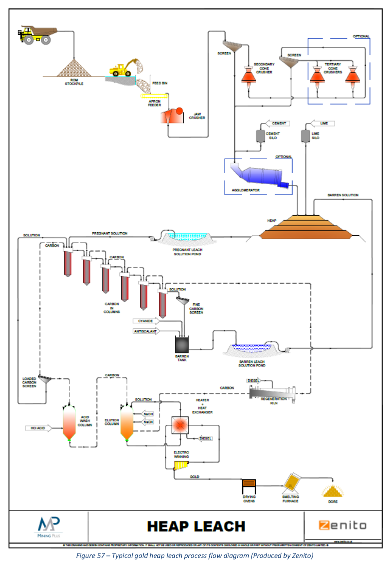
This conceptual study proposes a heap leach processing route for oxide material at 1.5 million tonnes per annum, based on limited historical testwork and regional analogues.
Report context
The Preliminary Economic Assessment (PEA) for the Diba project was prepared for Altus Strategies and reports on a processing concept developed from limited metallurgical test work commissioned by Etruscan in 2012 and conducted by Endeavour Mining’s Tabakoto mine, together with observations from other operations in the region. At this preliminary stage, no detailed design for the heap leaching has been completed, so the proposed system is considered conceptual only.
Processing route
Crushing
A two-stage crushing circuit has been proposed to reduce run-of-mine oxide material to finer than 25 mm. The crushing circuit will include a jaw crusher, a vibrating screen, a cone crusher, an optional agglomerator and related mobile conveyors. Run-of-mine material will be transported from the open pit to the crushing plant by haul trucks and dumped into a run-of-mine bin feeding a belt conveyor to the primary jaw crusher. A front-end loader will reclaim stocked run-of-mine material into the bin according to the mine plan. The jaw crusher product will be discharged onto a second belt conveyor and fed onto a vibrating screen to remove undersize material from the feed to the secondary cone crusher. Screen oversize will report into a surge bin ahead of the secondary cone crusher. The discharge of the cone crusher is planned to be finer than 25 mm. Further studies are required to test the crushing circuit and understand the size fractions likely to be produced at each stage of crushing. If significant fine material is produced then an agglomerator will need to be added to the process. The undersize material from the vibrating screen and the crushed material from the cone crusher will feed onto a common conveyor that will transport the material to an agglomerator. Cement will be added to the content on the conveyor as it feeds into the agglomerator. Spray water will be added into the agglomerator to improve agglomeration efficiency. Lime will also be added to the crushed material before placement to control the alkalinity of the heap leach. The agglomerated material will discharge onto a crushed material stockpile adjacent to the crushing plant for curing.
Heap Leaching
The heap leach pad will be an engineered structure consisting of a gravel or sand base covered with a clay liner, then covered with an impermeable synthetic geomembrane. Impermeable berms will surround the perimeter of the leach pad. The pad will gently slope to a central pregnant leach solution collection pond on the downside of the pad, which will also have an impermeable geotextile liner. The leach pad will be designed to withstand the loading of crushed material and the movement of heavy equipment on top. A leak detection and recovery system including ground wells will be installed at the heap leach pad and the solution ponds.
The crushed and agglomerated material will be reclaimed from the stockpile with a front-end loader and loaded into a haul truck for transport to the heap leach pad. The material will be stacked onto the heap pad in 5 m lifts. A bulldozer will be used to spread the material evenly on the leach pad. The final heap is expected to cover an area of approximately 250,000 m², with an average vertical height of 15 m (3 x 5 m high lifts). A detailed stacking plan and irrigation plan will be developed for the next level of study.
Barren leach solution will be pumped to the top of the heap leach pad and distributed through drip emitters onto the surface at an overall solution feeding rate of approximately 8 to 10 L/h/m², leaching the gold during a 100-day cycle. The cyanide solution will percolate down through the heap, dissolving the gold, and the gold-bearing leachate will be collected in the pregnant leach solution pond.
Four lined solution ponds are planned: one pregnant leach solution pond, one barren leach solution pond, one event or overflow solution pond, and one polishing pond. The solution from the barren solution pond will be pumped to the leach heap. Concentrated cyanide solution will be added to the barren solution pond to give a controlled cyanide concentration of approximately 0.5 to 1.0 g/L sodium cyanide strength. The pH will be maintained at 10.5 or higher. The event pond will temporarily store excess process solution that may occur during seasonal conditions; this solution will be recycled back into the heap leach circuit when regular operation resumes. Excess solution collected during the wet season will be treated with calcium hypochlorite and discharged into the polishing pond to reduce cyanide levels to acceptable limits before discharge to the environment.
The proposed height for the heap would require geotechnical verification and further metallurgical test work confirmation. The preliminary site layout and available space, site drainage, and pad size are designed according to the area topography and the best available information.
Carbon-in-Column Recovery and Refining
The pregnant leach solution will be pumped to the Carbon-in-Column (CIC) facility for gold recovery. The solution will first go to a pressure clarifier to remove suspended solids, then to a de-aeration tower operating under vacuum to remove oxygen. From the de-aeration tower, the solution will flow into a series of carbon columns charged with activated carbon. The gold will adsorb onto the surface of the carbon. The loaded carbon will be periodically removed from the columns and sent to the stripping circuit, where a heated solution of sodium hydroxide and cyanide will re-dissolve the gold from the carbon surface. The gold-bearing solution will be sent to electrowinning cells, where the gold will be plated onto stainless steel cathodes. The gold will be removed from the cathodes using a high-pressure water spray. The fine, powdered gold will then be melted in a smelting furnace and poured into moulds to produce doré bars. The slag from the furnace will be collected and occasionally re-smelted to recover small amounts of gold. Once stripped, the carbon will be reused after recharging in a kiln by heating to around 1300 degrees F, then cooling and screening to remove fines.
The barren leach solution from the CIC facility will be pumped to the barren leach solution pond where the solution will be conditioned with lime and cyanide to a concentration of approximately 0.5 to 1.0 g/L sodium cyanide and a pH of 10.5 or higher, prior to recycling to the heap leach.
Water Supply
Two separate water supply systems for freshwater and process water will support the operation. Freshwater will be supplied to a fresh/fire water storage tank from the pits, nearby river, and/or from wells, and will be used primarily for fire water for emergency use, slurry pumps, and reagent makeup. The fresh/fire water tank will be equipped with a standpipe ensuring a minimum 2-hour supply of fire water. Potable water supply will be drawn from the nearby river separately, treated, and stored in a potable water storage tank prior to delivery to various service points. Process water will be required for agglomeration and heap leach pad irrigation. The barren leach solution from the CIC circuit will be reused for heap leach irrigation. Due to water loss and evaporation, freshwater will also be required to supplement the process water, especially during the dry months, expected to come from the pit, runoff catchment, and wells.
Air Supply
Separate air service systems will supply high-pressure air from a portable air compressor for the crushing area, high-pressure air by dedicated air compressors for the CIC circuit, and instrument air from the air compressors at the CIC facility, which will be dried and stored in a dedicated air receiver.
Key reported parameters
| Parameter | Value | Basis |
|---|---|---|
| Throughput rate | 1.5 million t/a (approx. 4,100 t/d) | Proposed design concept |
| Crushing product size | Finer than 25 mm | Proposed design target |
| Heap lift height | 5 m per lift; final heap 15 m (3 lifts) | Proposed design |
| Heap pad area | Approx. 250,000 m² | Proposed design estimate |
| Leach cycle duration | 100 days | Proposed design |
| Solution application rate | 8 to 10 L/h/m² | Proposed design |
| Cyanide concentration in barren solution | 0.5 to 1.0 g/L NaCN | Proposed design |
| Solution pH target | 10.5 or higher | Proposed design |
| Testwork source | Limited metallurgical test work commissioned by Etruscan in 2012, conducted by Endeavour Mining’s Tabakoto mine | Historical testwork |
| Operating basis | Similar to existing operating heap leach mines processing similar material under comparable conditions | Analogy-based |
| Operating schedule | Crushing, leaching and gold recovery: 24 hours/day, 7 days/week; leaching on stacked material continuous year-round | Proposed design |
Project website: https://www.northernminer.com/news/etruscan-confirms-good-grades-in-mali/1000054159/
Technical qualifications
- No detailed design for the heap leaching has been completed; the proposed system must be considered as conceptual only at this point in time.
- The proposed height for the heap would require geotechnical verification and further metallurgical test work confirmation.
- Further studies are required to test the crushing circuit and understand the size fractions likely to be produced at each stage of crushing.
- A detailed stacking plan and irrigation plan will be developed for the next level of study.
Source: *Altus Strategies Diba Project Updated Preliminary Economic Assessment*, Section 17 Recovery Methods.
