

The NioCorp developments Ltd. feasibility study for the Elk Creek project in Nebraska describes a processing facility divided into three integrated plants: mineral processing, hydrometallurgical, and pyrometallurgical. The operation would produce ferroniobium, scandium oxide, titanium tetrachloride, neodymium/praseodymium oxide, terbium oxide, dysprosium oxide, samarium-europium-gadolinium carbonate, and holmium-erbium-thulium-ytterbium-lutetium-yttrium carbonate from the Elk Creek deposit.
NioCorp Developments Ltd.’s Elk Creek project is located in Nebraska. The project is a feasibility study. The target commodities include niobium, scandium, titanium, and rare earth elements. The technical report is dated August 10, 2026. Construction timing is not stated in the supplied source material.
Critical Data
| Parameter | Value | Unit | Notes |
|---|---|---|---|
| Annual design throughput (mineral processing) | 1,008,129 | t/a | Design value |
| Process plant throughput (mineral processing) | 125 | t/h | Design value |
| Available time (mineral processing) | 7,232 | h/a | Design value |
| Availability (mineral processing) | 85 | % | Design value |
| Process plant throughput (hydrometallurgical) | 126.9 | mt/h | Design value |
| Available time (hydrometallurgical) | 7,920 | h/a | Design value |
| Availability (hydrometallurgical) | 90.4 | % | Design value |
| Primary crusher product size (P80) | 115 | mm | Design value |
| Final comminution product size (P80) | 1.1 | mm | Design value |
| Ore activation calciner discharge temperature | 1,454 | °F | Test result |
| FeNb furnace operating temperature | 1,700 to 1,775 | °C | Design value |
| FeNb furnace design power | 1,000 | kW | Design value |
| Nb recovery to metal (pyrometallurgical) | 96.6 | % | Modeled value |
| FeNb daily production | 22.4 | t/d | Design value |
| Hydrometallurgy installed power | 13,431 | kVA | Design value |
| Solvent extraction installed power | 739 | kVA | Design value |
| Hydrochloric acid regen installed power | 4,691 | kVA | Design value |
| Total hydrometallurgical installed power | 18,861 | kVA | Design value |
| Pyrometallurgical total installed power | 5,200 | kVA | Design value |
Overview
The processing facility is designed to recover ferroniobium, scandium oxide, titanium tetrachloride, neodymium/praseodymium oxide, terbium oxide, dysprosium oxide, samarium-europium-gadolinium carbonate, and holmium-erbium-thulium-ytterbium-lutetium-yttrium carbonate. The facility is divided into three plants: a mineral process plant, a hydrometallurgical plant, and a pyrometallurgical plant. The hydrometallurgical plant is divided into nine areas.
Run of mine ore is stockpiled on surface and fed to a jaw crusher. The jaw crusher product is stored in a three-bin system and conveyed to the mineral processing plant. The mineral processing plant contains a High-Pressure Grinding Roll and cone crusher in closed circuit with screens to produce a uniform 1 mm product suitable for hydrometallurgical processing.
Ore from the mineral processing unit is first activated in a rotary calciner to convert carbonate to oxides. Two of the main impurities, calcium and magnesium, are then sequentially leached and mineralized using an ammonium chloride cycle circuit. The ammonium chloride cycle leach residue, depleted in calcium and magnesium, is then subjected to a two-stage counter-current hydrochloric acid leach where iron, rare earths, and scandium are solubilized.
The resulting pregnant leach solution is contacted with a DGA-6 organic solution to selectively recover rare earths and scandium. The rare earth and scandium strip liquor is then sent to the REE separation unit where the rare earth elements and scandium are separated and recovered as individual oxide or mixed-carbonate products.
The residue from the hydrochloric acid leach unit is dried before being subjected to a sulfuric acid bake where the niobium and titanium minerals are decomposed to soluble sulfate compounds. The residue from the acid bake process is leached with water and the non-soluble impurities are sent to paste backfill. The sulfate leach solution, rich in niobium and titanium, is hydrolyzed and the resulting hydrolysate, a combination of niobium and titanium compounds, is dewatered and calcined.
The calcined hydrolysate is chlorinated, converting both niobium and titanium into their respective chlorides. The vapor is then sequentially condensed and distilled to yield a pure titanium tetrachloride product and a crude niobium chloride product. The crude niobium chloride product is then leached using water and re-hydrolyzed to generate a niobium oxide product which is subsequently converted into ferroniobium in the pyrometallurgical plant.
The chloride effluent from REE extraction is concentrated and pyro-hydrolyzed to produce a mixed-oxide by-product, regenerating the hydrochloric acid used in the hydrochloric acid leach unit. All sulfate effluents are combined and neutralized using a combination of calcium carbonate and quicklime to precipitate all base metals as hydroxides and generate a treated water stream.
The solid effluents from the process are recovered and sent to the paste backfill plant, where they are pumped underground as a structural paste backfill or pumped to the tailings impoundments for disposal.
Key Process Stages
Surface Crushing, Ore Storage, and Mineral Processing. The primary driver of the comminution circuit design is the dry processing of ore to avoid an expensive drying operation prior to acid leaching. The process design relies upon receiving a primary crusher product with a characteristic particle size of P80 115 mm at the comminution circuit feed bin and producing feed material for the downstream hydrometallurgical processing at a characteristic particle size of P80 1.1 mm.
The primary crusher product will be fed to the secondary cone crusher system, operating in closed circuit with a double deck screen. The screen undersize from the cone crusher system will be fed to an HPGR unit, operating in closed circuit with another double deck screen. The HPGR screen undersize is the comminution product that will report to the hydrometallurgical process.
ROM ore from the underground mine will be transported to a surface ROM stockpile located in front of the primary crushing circuit. The ore will be fed via grizzly feeder and screen to a C135 primary jaw crusher. The crushed product with a top size of 203 mm and characteristic size of 115 mm will be delivered by a three-way diverter splitter to three crushed ore bins each with a capacity of 1,400 tonnes. This part of the crushing circuit will operate on a 10 hours per day schedule. The subsequent crushing and the processing plant will operate 24 hours per day.
At the secondary crushing stage, the ore will be sized on a dry, double deck screen with a top deck aperture size of 50 mm and bottom deck aperture size of 25 mm. The screen oversize from both decks will report to the secondary crushing stage consisting of a single cone crusher unit. The screen undersize will be conveyed to the HPGR circuit. The recirculating load of the HPGR circuit is expected to be in the range of 30 to 40% of the circuit new feed.
The ore will be stored in a fine ore bin, then reclaimed by a vibrating feeder with a design capacity of 132 t/h, and then passed on to the acid leach circuit via the acid leach feed conveyor for further processing.
Ore Activation (Area 100). The ore activation area is used to convert the carbonate minerals in the feed material to oxides through thermal decomposition while recovering the CO₂ generated in the process. Activation of the feed ore is accomplished by heating the feed material to approximately 1,454°F (790°C) in the indirect natural gas rotary calciner. The conversion releases CO₂ gas that is captured, treated, and reused. Following the calcination process, the calcined ore is cooled in the activated material cooler and conveyed to Area 200.
Ammonium Chloride Cycle (Area 200). The ammonium chloride cycle area is used to selectively leach calcium and magnesium from the calcined ore feed material using a closed loop circuit. The calcium and magnesium are then sequentially recovered through carbonate mineralization, regenerating the ammonium chloride leach reactant, which is recycled to the leach circuit.
The ammonium chloride leach circuit selectively leaches calcium and magnesium from the calcined ore feed material. This leach reaction converts ammonium chloride into ammonium hydroxide which is partially vaporized and recovered. The stage 1 NH₄Cl Leach Circuit is composed of a cascade of three agitated tanks in series, each with external heating loops to maintain the reactors at their operating temperature.
The NH₄Cl Filtration circuit comprises three identical filtration trains. The slurry is filtered using plate and frame presses to separate the Ca/Mg-rich pregnant leach solution from the remaining oxide solids. The residue from the filters is combined and dried before being sent to Area 300.
The calcium carbonatation circuit mineralizes the calcium leached in the ammonium chloride process by converting it to solid calcium carbonate. The magnesium carbonatation circuit mineralizes the magnesium leached in the ammonium chloride process by converting it to solid magnesium carbonate.
Hydrochloric Acid Leach (Area 300). The hydrochloric acid leach area is used to leach the rare earth elements, including scandium, away from the niobium and titanium-containing minerals. Elements such as iron, calcium, thorium, and other impurities are also recovered in the chloride pregnant leach solution.
A counter-current system is used to maximize recovery and control the acidity of the PLS prior to extraction in Area 600. NHL residue from Area 200 is combined with 2nd stage leach filtrate, 2nd stage leach wash solution, and 1st stage leach wash solution into the HCl leach stage 1 cascade of agitated tanks. External recirculation flows are planned to maintain the leach reactors’ temperatures. Leach slurry from the 1st stage HCl leach step is dewatered in a 2-step hydrocyclone unit. The cyclone underflow is sent to the 2nd stage HCl leach circuit. The residual slurry from the second HCl leach stage is sent to Unit 320 for dewatering.
Sulfuric Acid (Area 400). The sulfuric acid area converts the Nb and Ti-bearing minerals to leachable sulfate compounds. The resulting sulfates are then leached using water. Both the niobium and titanium sulfate compounds are hydrolyzed before being dewatered, calcined, and sent to Area 500 for further processing.
The acid baking unit reacts HCl leach residue, a Nb and Ti rich solid, with concentrated sulfuric acid at elevated temperatures to convert the minerals to solid anhydrous sulfates. Vaporized sulfuric acid is recovered and recycled in the circuit using a 2-step scrubbing circuit. Dry HCl leach residue is combined with hot, concentrated sulfuric acid and mixed thoroughly in a pug mill, then conveyed to the Acid Bake Kiln.
The water leaching circuit solubilizes the sulfate compounds from the acid bake process into an aqueous phase, leaving the insoluble contaminants in the solid residue. The resulting slurry is pumped into the water leach cascade of three agitated tanks, each maintained at a temperature of 176°F (80°C) with a circulation heating loop.
The hydrolysis unit converts soluble niobium and titanium sulfates compounds into insoluble compounds comprised of a mixture of oxide, hydroxide, and oxy-hydroxy-sulfates.
Chlorination (Area 500). The chlorination area converts hydrolysate cake to gaseous metal chlorides and recovers each element individually. Niobium and iron are first solidified in a titanium tetrachloride slurry. The titanium tetrachloride is subsequently vaporized. The mixture of niobium and iron chloride is hydrolyzed. Niobium is recovered as an oxide with iron residuals. The crude titanium tetrachloride solution is then distilled into a pure titanium tetrachloride product.
The chlorination unit uses a fluid bed reactor. Hydrolysate cake is mixed with petroleum coke and fed to the chlorinator. The gaseous discharge of the chlorinator is filtered and sent to the condensation circuit. The Nb/Fe condenser solidifies and recovers niobium and iron chloride in a titanium tetrachloride slurry. The primary condenser condenses a titanium tetrachloride solution. The secondary condenser also condenses a titanium tetrachloride solution.
The TiCl₄ purification unit prepares pure TiCl₄ that meets commercial purity specifications using a combination of stripping and distillation.
Rare Earth Element Extraction (Area 600). Area 600 involves the extraction of scandium and rare earth elements from the HCl pregnant leach solution generated in Area 300 and the preparation of a REE solution to feed Area 700. The REE Recovery Area uses dimethyloctyl dihexyl diglycolamide (DGA-6) diluted in ethyl-hexanol.
The REE Extraction circuit uses an organic solution made of 50 v% DGA-6 diluted in Ethyl-Hexanol. Barren organic from the REE strip circuit is contacted with HCl PLS in a Karr Column, extracting scandium and rare earth elements. The loaded organic is scrubbed in a second Karr column using a dilute hydrochloric acid and magnesium chloride solution. The scrubbed organic is sent to the acid scrub circuit, which removes residual hydrochloric acid along with a significant portion of the co-extracted iron.
The REE Strip circuit recovers the rare earth elements from the loaded organic using a low activity magnesium chloride solution. Scrubbed organic is pumped through a series of 4 mixer-settlers installed in co-current fashion.
Rare Earth Separation (Area 700). Area 700 involves the separation of magnetic rare earth elements and of scandium from the mixed rare earth strip liquor and the precipitation of four commercial products and 2 by-products using conventional solvent extraction technology. Products include didymium oxide, terbium oxide, dysprosium oxide, and scandium oxide. By-products include mixed samarium, europium, and gadolinium (SEG) carbonates and mixed heavy rare earths and yttrium (HREY) carbonates.
The neutralized strip liquor is separated in the Primary Circuit into four fractions: a raffinate solution containing light rare earths, a mid-fraction containing SEG, a heavy rare earth fraction, and scandium is recovered from the organic through prestripitation.
The three magnetic rare earths products are precipitated using oxalic acid and calcined to oxide. The two byproducts are precipitated using ammonium carbonate and dried.
Chloride Recovery (Area 800). The chloride recovery area is used to recover chloride ions as hydrochloric acid that can be recycled in the process. It is divided into three sections: ferric chloride, other chlorides, and hydrochloric acid recovery. The ferric chloride section uses ferric chloride pyro-hydrolysis, while the other chloride section uses a pyro-hydrolysis based magnesium cycle to recover most chloride ions as hydrochloric acid.
Sulfate Effluent Treatment (Area 900). The sulfate effluent area treats the sulfate effluent and generates tailings that can be used for paste backfill. All sulfate effluents are neutralized simultaneously in a cascade of agitated tanks using calcium carbonate from Area 200 to reach a pH of 4.5. The discharge is further neutralized to a pH of 8 using calcium oxide.
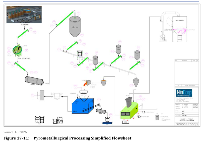
Pyrometallurgical Plant. The selected process is based on the aluminothermic reduction of oxide phases produced during the calcination step, following the hydrometallurgical niobium precipitation stage. A disc pelletization stage is incorporated immediately downstream of the final hydrometallurgical precipitation step. The pellets are subsequently calcined to produce a stable oxide phase for pyrometallurgical processing.
The calcined material is conveyed to the Furnace Feed Preparation Area and stored in a closed bin providing approximately eleven days of storage capacity. Aluminum and hematite (Fe₂O₃) are stored in dedicated bins, each designed to provide approximately fourteen days of storage capacity. Fluxing agents, including calcium carbonate and calcium fluoride, are stored separately.
The process is operated on a batch basis. The prepared charge is introduced into an induction furnace, where temperature is progressively increased until the aluminothermic reaction is initiated. The FeNb induction furnace operates within a temperature range of approximately 3,092°F to 3,227°F (1,700°C to 1,775°C). Electrical energy is supplied to heat the furnace charge and initiate the aluminothermic reaction.
Molten FeNb alloy is tapped through a refractory-lined launder into a pelletizing pan and granulated in a water basin to produce pellets typically ranging from 6 to 15 mm in diameter.
Additional Interesting Data and Summary
The hydrometallurgical plant building is a large multi-level engineered steel structure with dimensions approximately 550 ft x 200 ft (167.64 m x 60.96 m) with a 100 ft (30.5 m) eave height. The pyrometallurgical building is an engineered steel structure with dimensions approximately 45.7 m x 45.7 m (150 ft x 150 ft) with a 22.9 m (75 ft) eave height.
The overall recoveries for saleable products across the flowsheet, as derived from mass balance integration using an averaged feed composition, are 80.5% for titanium, 84.7% for niobium, 94.3% for scandium, 88.7% for praseodymium, 94.4% for neodymium, 94.4% for terbium, and 94.6% for dysprosium. The technical report notes that pay element recovery variations are to be expected during facility operation and that the difference is within the expected uncertainty margin at this stage of project development.
The modeled niobium recovery to the alloy in the pyrometallurgical plant is approximately 96.6% and is subject to confirmation during industrial operation. The required NaNbO₃ feed rate is estimated at 26.6 t/d (dry basis), equivalent to 1.11 t/h.
The pyrometallurgical plant is designed to produce 22.4 tons per day of FeNb alloy containing approximately 64.9% Nb and 34.0% Fe.
Key Processes
- Surface crushing uses a jaw crusher, secondary cone crusher, and HPGR in closed circuit with screens for dry processing.
- Ore activation converts carbonates to oxides in a rotary calciner at approximately 1,454°F.
- Ammonium chloride leach selectively removes calcium and magnesium from calcined ore.
- Calcium and magnesium are recovered as carbonates, regenerating the ammonium chloride leach reagent.
- Two-stage counter-current hydrochloric acid leach solubilizes iron, rare earths, and scandium.
- Solvent extraction with DGA-6 selectively recovers rare earths and scandium from the HCl pregnant leach solution.
- Sulfuric acid bake decomposes niobium and titanium minerals to soluble sulfate compounds.
- Water leaching solubilizes sulfate compounds, followed by hydrolysis to precipitate niobium and titanium compounds.
- Chlorination in a fluid bed reactor converts hydrolysate to metal chlorides for separation.
- TiCl₄ purification uses stripping and distillation to produce a pure product.
- Nb recovery involves hydrolysis of niobium chloride, dewatering, and calcination to niobium oxide.
- Rare earth separation uses conventional solvent extraction with Cyanex extractants in multiple circuits.
- REE products are precipitated as oxalates (NdPr, Tb, Dy) or carbonates (SEG, HREY) and calcined or dried.
- Scandium is recovered from the organic phase by sodium hydroxide prestripitation.
- Scandium purification uses batch solvent extraction with Alamine 336 and Aliquat 336.
- Chloride recovery uses pyro-hydrolysis to regenerate hydrochloric acid from process effluents.
- Sulfate effluents are neutralized with calcium carbonate and quicklime to produce a treated water stream.
- Pyrometallurgical processing uses aluminothermic reduction in an induction furnace to produce ferroniobium.
Source: NI 43-101 Technical Report – Elk Creek Feasibility Study, August 10, 2026. Project website: Elk Creek
