

The Tiros Rare Earths and Titanium Project is a preliminary economic assessment stage project located in Minas Gerais, Brazil, owned by Resouro Strategic Metals Inc. The project targets rare earth elements and titanium from anatase-bearing feed material. Construction timing is not stated in the source material.
Critical Data
| Parameter | Value | Unit | Notes |
|---|---|---|---|
| Plant feed | 500,000 | t/a | ROM mineralized material |
| Feed TiO₂ grade | 26.3 | % | Average |
| Feed Fe₂O₃ grade | 31.95 | % | Average |
| Feed Al₂O₃ grade | 11.47 | % | Average |
| Feed SiO₂ grade | 22.95 | % | Average |
| Feed TREO grade | 10,852 | ppm | Average |
| Operating days | 365 | d/a | Design value |
| Operating availability | 92 | % | Design value |
| Operating hours per year | 8,059 | h/a | At stated availability |
| Fine TiO₂ product | 47,865 | t/a | Design value |
| Coarse TiO₂ product | 42,390 | t/a | Design value |
| Global TiO₂ recovery | 68.7 | % | Design value |
| Feed TREO | 5,426 | t/a | Design value |
| TREO recovered in MREC | 3,636 | t/a | Approximate design value |
| Global TREO recovery | 67.0 | % | Design value |
| MREC production rate | Not stated | t/a | To be confirmed |
| MREC TREO grade | Not stated | % | To be confirmed |
| Total raw water requirement | 391 | m³/h | Projected design value |
| Coarse area water consumption | 130 | m³/h | Design value |
| Fine area water consumption | 54.5 | m³/h | Design value |
| Reagents water consumption | 154 | m³/h | Design value |
| Cooling water make-up | 1.89 | m³/h | Design value |
| Other water consumption | 50.7 | m³/h | Design value |
| LIMS field strength (coarse circuit, first stage) | 1,000 | Gauss | Design value |
| LIMS field strength (coarse circuit, second stage) | 2,000 | G | Design value |
| LIMS field strength (fines circuit) | 800 | Gauss | Design value |
| Calcination temperature | 600 | °C | Design value |
| Calcination residence time | 60 | minutes | Design value |
| Post-kiln air cooling target | 100 | °C | Design value |
| Post-kiln water cooling target | 50 | °C | Design value |
| Acid baking temperature | 300 | °C | Design value |
| Acid baking residence time | ~1 | hour | Design value |
| HCl leaching temperature | 90–100 | °C | Design value |
| HCl leaching time | ~90 | minutes | Design value |
| HCl leach solution concentration | ~16 | wt% | Design value |
| HCl consumption | 0.056 | t/t ROM | Active HCl; design value |
| HCl consumption as 34% solution | 0.164 | t/t ROM | Design value |
| Coarse area HCl consumption | 82,192 | t/a | Design value |
| Coarse area CO consumption | 685 | t/a | Design value |
| Fine area Mg(OH)₂ (95%) consumption | 2,397 | t/a | Design value |
| Fine area Na₂CO₃ (95%) consumption | 3,725 | t/a | Design value |
| Fine area CO consumption | 10,205 | t/a | Design value |
| Fine area H₂SO₄ (96%) consumption | 186,986 | t/a | Design value |
| Fine area NaOH (98%) consumption | 102,534 | t/a | Design value |
Overview
The Tiros deposit is shallow, soft, and highly weathered. That makes the material friable and easy to handle. Conventional crushing and milling equipment for hard rock is not required. The flowsheet relies on disaggregation and size classification.
The processing plant is designed to produce upgraded titanium products and a Mixed Rare Earth Carbonate. Two main circuits are used. The coarse circuit handles material between 75 µm and 300 µm and produces an upgraded anatase concentrate. The fines circuit handles material below 75 µm and produces a fine titanium product plus an MREC.
Key Process Stages
The ROM mineralized material is trucked to the plant and fed into a scrubber inlet screen for initial separation. The scrubber is a trommel scrubber. It is a rotating cylindrical drum with an internal washing and disaggregation section and a perforated screening section at the discharge end. Agglomerates and clay crusts break down inside the drum. Process water is fed at high pressure to disperse clays and detach fine TiO₂ and REE particles from coarser fragments. Material that meets the required particle size passes through the perforations as slurry. Oversized lumps discharge to the tailings area.
Disaggregated material goes to a screen with a 300 µm cut size. Material over 300 µm goes to a rod mill. The rod mill has a perforated screening section at the discharge end that separates material smaller than 300 µm. Undersize recirculates to the screen. Oversized lumps go to tailings.
Material under 300 µm goes to a second screen with a 75 µm cut size. Material between 75 µm and 300 µm goes to the coarse circuit. Material below 75 µm goes to the fines circuit for REE recovery.
In the coarse circuit, the 75–300 µm material is fed to a low intensity magnetic separator operating at 1,000 Gauss. Process water is added. Iron content drops from 42.3% to 17.4% in the non-magnetic fraction. The magnetic fraction goes to a thickener and filter. Overflow from the thickener goes to water treatment. Filtrate returns to the thickener. Wet solid goes to tailings.
The non-magnetic fraction goes to a gravimetric separation unit. Silicon content drops from 16.0% to 4.5% SiO₂ in the heavy fraction. The light fraction is high in kaolinite and quartz and goes to a thickener and filter.
The heavy fraction goes to a thickener and filter for solid–liquid separation. Overflow goes to water treatment. Filtrate returns to the thickener.
The filter cake goes to a rotary kiln. The upstream section dries and preheats the material. Calcination takes place at 600°C for 60 minutes under a controlled atmosphere. Carbon monoxide is used as the reducing agent. It is generated externally in a dedicated unit and introduced as a CO-rich gas stream. Iron reduces from Fe³⁺ to Fe²⁺, increasing magnetic susceptibility. Off gases go through a dedicated gas handling and treatment system.
The discharge from the rotary kiln is at approximately 600°C. An air-cooling unit reduces the temperature to approximately 100°C. A water-cooling stage further reduces it to around 50°C.
The cooled material goes to a LIMS operating at approximately 2,000 G. This removes residual iron-bearing minerals. Iron content in the non-magnetic product drops to approximately 5% Fe. The magnetic fraction goes to the tailings storage facility.
The non-magnetic fraction goes to electrostatic separation. This exploits differences in electrical conductivity. Feed material must be dry. Conductive and non-conductive particles follow different trajectories. Silicon-containing minerals are recovered in the non-conductor fraction and go to tailings. Anatase reports to the conductor fraction. SiO₂ in the conductor material drops to less than 1.0%.
The conductive fraction undergoes hydrochloric acid leaching at 90–100°C for approximately 90 minutes. The leach solution contains approximately 16 wt% HCl. Hydrochloric acid consumption is approximately 0.056 tonne of active HCl per tonne of ROM. That is equivalent to 0.164 tonne of 34% HCl solution as supplied per tonne of ROM. The upgraded anatase concentrate has an anticipated TiO₂ grade exceeding 80%. This is the proposed coarse titanium product. Its suitability for conventional pigment production and chlorination performance remain to be confirmed.
In the fines circuit, material passing 75 µm goes to a LIMS operating at 800 Gauss. The magnetic fraction is mostly iron and goes to a thickener and filter for tailings disposal and liquid recovery.
The non-magnetic fraction goes to a rotary kiln. The material is dried and preheated in the initial section. Discharge is at approximately 600°C. Air cooling reduces it to approximately 100°C. Water cooling reduces it to 50°C. The material then goes to a dry magnetic separator. The magnetic fraction goes to tailings.
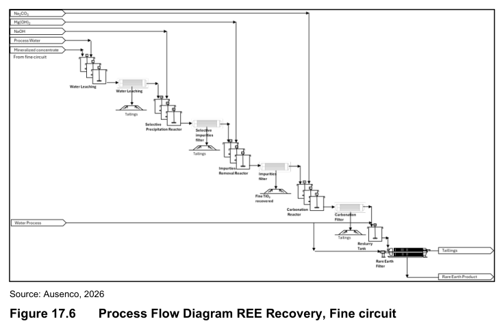
The non-magnetic fraction goes to an acid baking rotary kiln. Concentrated sulfuric acid is mixed with the material to form a reactive paste. Thermal treatment is at 300°C for approximately one hour. REE are converted to soluble sulfates. Fe, Al, and Ti also react. An acid-regeneration unit has been assumed in the process design. It is proposed to operate at approximately 600°C. Acid regeneration is a conceptual and untested design assumption at the PEA stage.
The calcine is cooled and transferred to agitated leaching reactors. Sequential washing with water dissolves the REE sulfates along with Fe, Al, and Ti sulfates. Non-converted minerals, primarily SiO₂, remain undissolved. Solid–liquid separation in a filter produces a clarified liquor and a low-moisture solid residue that goes to tailings.
A subsequent stage is proposed for titanium removal. The clarified sulfate liquor undergoes controlled neutralization using 10 wt% NaOH in agitated reactors. Hydrated titanium oxide precipitates. Titanium-bearing solids are recovered by filtration. This step has not been demonstrated for the Tiros process liquor. Sodium–rare earth double sulfates may precipitate and cause REE losses. Future testwork should confirm titanium-removal selectivity.
The REE-bearing liquor goes through purification. Mg(OH)₂ is added in impurity removal agitated reactors. In the first reactor, Mg(OH)₂ increases pH and promotes precipitation of iron and aluminum. Further Mg(OH)₂ addition adjusts pH for precipitation of potassium, calcium, and other ions. REE remain in solution. Filtration produces a clarified liquor and a low-moisture filter cake for disposal.
The purified REE liquor goes to precipitation agitated reactors. A sodium carbonate solution is added under controlled pH and temperature. MREC precipitates. The slurry is filtered. The solid MREC goes to a reslurry tank for washing to reduce residual impurities. The washed slurry is dewatered in a filter press. The MREC product is suitable for downstream separation and refining.
The total projected raw water requirement is approximately 391 m³/h. Water will be sourced from local catchments. It supplies process water, demineralized water, and cooling water make-up. Demineralized water is used for reagent preparation and acid dilution. A water treatment plant is planned to process liquid streams from solid–liquid separation stages for conditioning and reuse. The design of the Water Recovery System will be undertaken in the next study phase.
Carbon monoxide for both circuits is produced from charcoal through combustion and calcination. Hydrochloric acid is delivered in tanker trucks and diluted to 16% with process water. Sulfuric acid is received at 96% concentration. Sodium hydroxide is received as bagged solid and dissolved to a 10% solution. Magnesium hydroxide is received as bagged solid and prepared as a 10 wt% slurry. Sodium carbonate solution is prepared at 25% w/w. Diesel is used for backup electricity generation. LPG is used for kiln equipment.
Additional Interesting Data and Summary
The process design criteria were developed on a preliminary PEA basis. The mass balance is based on laboratory testwork by Resouro along with preliminary design assumptions and benchmarks from analogous operations. Process conditions should be considered preliminary.
At the stated plant throughput and feed grade, the feed contains approximately 5,426 t/a TREO. Of that, approximately 3,636 t/a TREO is estimated to report to the MREC. The MREC production rate, composition, and TREO grade remain subject to confirmation.
The LIMS in the coarse circuit reduces iron content from 42.3% to 17.4% in the non-magnetic fraction. The gravimetric separation lowers silicon content from 16.0% to 4.5% SiO₂ in the heavy fraction. After the second LIMS, iron content in the non-magnetic product is approximately 5% Fe. Electrostatic separation reduces SiO₂ to less than 1.0% in the conductor material. The final anatase concentrate is anticipated to exceed 80% TiO₂.
Key Processes
- Scrubbing and size classification for feed preparation
- Low intensity magnetic separation for iron removal
- Gravimetric separation for silicon removal
- Reductive calcination with carbon monoxide
- Dry magnetic separation after calcination
- Electrostatic separation for final silica rejection
- Hydrochloric acid leaching for anatase upgrading
- Acid baking with sulfuric acid for REE conversion
- Water leaching of calcine
- Selective precipitation of titanium using sodium hydroxide
- Impurity removal with magnesium hydroxide
- MREC precipitation with sodium carbonate
- Solid–liquid separation at multiple stages throughout the flowsheet
Source: NI 43-101 Technical Report and Preliminary Economic Assessment for the Tiros Rare Earths and Titanium Project, Minas Gerais, Brazil, July 10, 2026. Project website: Tiros Rare Earths and Titanium Project
