

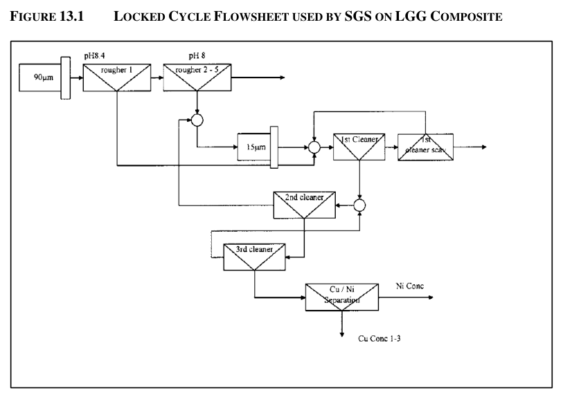
The Kenbridge Nickel Project preliminary economic assessment describes a conventional underground-sourced milling operation with a nominal capacity of 1,500 tpd and a surge capability of 2,000 tpd.
The Kenbridge Nickel Project is an underground mining operation planned to feed a conventional process plant designed for a nominal capacity of 1,500 tpd with a surge capability of 2,000 tpd. The processing facility will include crushing, grinding, flotation, concentrate thickening and filtration, and tailings thickening for backfill preparation and disposal. Metallurgical testwork on the Kenbridge Mineral Resource remains minimal, particularly in relation to producing separate copper and nickel concentrates. A continuous mini-pilot plant campaign has been considered to validate process variables such as grind sizes, retention times, and cleaner stages.
Mineralized material will be sourced from underground and handled through a primary jaw crusher located underground. The crusher could be as large as 700 mm by 700 mm (28 inches by 28 inches) with a 120 kW drive producing a -102 mm product. A grizzly above a bin in advance of the jaw crusher will have 450 mm square openings. Crushed material is drawn from a surge bin by an apron feeder discharging onto a conveyor equipped with metallic scrap removal magnets. Process plant feed will be transferred to skips, hoisted to surface, and delivered by conveyor from the headframe to a 5,000 t capacity covered stockpile near the process plant.
The stockpile will be drawn by at least three feeders to a grinding feed conveyor with a belt weightometer. A propane-fueled loader will manipulate the stockpile to reduce segregation by size and compensate for freezing. Grinding is proposed via a conventional SAG and ball mill circuit, with a target grind size P 80 of 90 µm. The SAG mill could have a pebble circuit, with +20 mm pebbles screened from SAG feed and recycled; pebble return is expected to be less than 5% of feed, making a pebble crusher optional. The ball mill will operate in closed circuit with two banks of cyclones arranged as one operating and one standby.
Flotation will produce a medium grade copper-nickel bulk concentrate through a rougher-scavenger circuit with a retention time of 20 minutes. The rougher-scavenger concentrate will be finely ground to approximately P 80 20-25 µm in a regrind mill; a vertical attrition-grinding mill with ceramic media may be preferred. A little more than 6% of the process plant feed, equivalent to 150 tpd or 8.3 t/h, will report to the regrind mill and subsequent flotation circuits. The finely ground bulk concentrate will be cleaned at least twice, with the final bulk cleaner concentrate directed to a copper-nickel separation flotation step. Tailings from this separation will report to a nickel concentration and cleaner circuit, with the copper concentrate possibly subject to additional copper cleaner stages. Column flotation cells may be used in the copper-nickel separation to reduce nickel distribution to the copper concentrate through froth washing.
XRD analyses by Xstrata indicated that pyrrhotite in both copper and nickel concentrates was the magnetically-susceptible monoclinic variety, suggesting both concentrates could be upgraded by magnetic separation. Regrinding of the bulk concentrate may not be required given mineralogical examination indicated relatively high liberation of all sulphides in the rougher concentrate; very fine grinding could reduce flotation kinetics and complicate copper-nickel separation.
Feed sorting using XRT technology was evaluated conceptually, with potential to reject on the order of 40% of ROM material and reduce the amount of material to be processed. However, in the absence of sorting test results, conventional crushing-grinding was selected for this PEA.
Tailings will be transferred to a backfill plant, possibly in a separate structure, and thickened to approximately 55% solids using a conventional hi-rate thickener. Fines will be separated by cyclones, with the coarse fraction used for hydraulic cemented backfill. Residual fines will be thickened to approximately 45% solids and sent to a conventional tailings facility with lined embankments. Process water will combine tailings thickener reclaim water and tailings facility reclaim water, subject to confirmation that thickener overflow water quality is not detrimental to flotation performance; mine water is an additional potential source.
Critical Data
| Parameter | Value | Unit | Notes |
|---|---|---|---|
| Nominal plant capacity | 1,500 | tpd | Design basis |
| Surge capability | 2,000 | tpd | Not stated |
| Primary crusher size | 700 by 700 | mm | Equivalent to 28 inches by 28 inches; 120 kW drive |
| Primary crusher product | -102 | mm | Not stated |
| Grizzly opening | 450 | mm | Square openings |
| Covered stockpile capacity | 5,000 | t | Not stated |
| Target grind size | 90 | µm | P 80 |
| SAG mill dimensions | 5 by 4 | m | Diameter by length; approximate |
| Ball mill dimensions | 5 by 7 | m | Diameter by length; approximate |
| Rougher-scavenger retention time | 20 | min | Not stated |
| Regrind target size | 20-25 | µm | P 80; approximate |
| Regrind mill feed | 150 | tpd | Equivalent to 8.3 t/h; slightly more than 6% of plant feed |
| Tailings thickener solids | 55 | % | Approximate |
| Fine tailings thickener solids | 45 | % | Approximate |
| Pebble return | <5 | % of feed | Not stated |
Overview
The Kenbridge Nickel Project process plant will be a conventional facility treating underground-sourced mineralized material at a nominal 1,500 tpd with a 2,000 tpd surge capability. The flowsheet includes underground primary crushing, SAG/ball mill grinding, bulk flotation with regrind and cleaning stages, copper-nickel separation, concentrate filtration, and a backfill plant for tailings management. The design is based on limited metallurgical testwork, with several process parameters remaining to be validated through pilot plant testing.
Key Process Stages
Mineralized material from underground will be crushed by a primary jaw crusher located underground, with the crushed product conveyed to a 5,000 t covered stockpile. Grinding will occur in a SAG mill followed by a ball mill in closed circuit with cyclones to achieve a target grind size of P 80 90 µm.
Flotation will produce a medium grade copper-nickel bulk concentrate in a rougher-scavenger circuit. The bulk concentrate will be reground to approximately P 80 20-25 µm and cleaned at least twice before copper-nickel separation. Column flotation cells may be used in cleaners to improve separation efficiency through froth washing.
Concentrates will be separately thickened and filtered using plate and frame pressure filters, up to four units providing backup capacity. Filtered concentrate moisture is expected to be approximately 10% or slightly greater. No on-site concentrate drying is proposed. Shipments will be as separate bulk nickel and copper concentrates in warm weather and in one tonne tote bags in colder weather, subject to confirmation of no liquefaction potential in transport.
Tailings will be thickened to approximately 55% solids, with the coarse fraction used for hydraulic cemented backfill. Residual fines thickened to approximately 45% solids will be sent to a lined conventional tailings facility. Process water will combine reclaim water from the tailings thickener and tailings facility, with mine water as an additional potential source.
Additional Interesting Data and Summary
In 2008, Xstrata conducted a detailed grinding design assessment using SGS laboratory 2006 data around a used 7.0 m by 2.7 m SAG mill, selecting a processing rate of 110 t/h, equivalent to 2,400 tpd with downtime. Xstrata's ball mill size estimate was 3.7 m diameter by 5.5 m long.
Based on the Authors' experience, steel ball consumption could be in the order of 3-4 kg/t, with energy draw approximately 25-30 kWh/t. Regrinding of the bulk concentrate may not be needed given mineralogical indication of relatively high liberation of all sulphides in the rougher concentrate. A continuous mini-pilot plant campaign has been considered to validate several process variables, including grind sizes, retention times, cleaner stages, use of column flotation in cleaners, and magnetic separation.
The copper concentrate would be expected to be approximately 35 dry tpd, while a copper-nickel concentrate may be as much as 120 dry tpd. Concentrates will be automatically sampled as thickener feed slurry, weighed, and manually sampled for each shipment using batch pipe-samplers after filtration.
Key Processes
- Crushing (underground primary jaw crusher, 700 by 700 mm, 120 kW, product -102 mm)
- Grinding (SAG mill plus ball mill in closed circuit with cyclones, target P 80 90 µm)
- Regrinding (approximately P 80 20-25 µm, vertical attrition mill with ceramic media may be preferred)
- Flotation (rougher-scavenger bulk circuit, 20 min retention, at least two cleaner stages)
- Copper-nickel separation (cleaner flotation, column flotation cells may be used)
- Magnetic separation (potentially applicable for upgrading both concentrates)
- Concentrate dewatering (conventional thickeners, plate and frame pressure filters)
- Tailings management (hi-rate thickener to 55% solids, cyclone for coarse fraction, backfill plant)
- Process water reclaim (tailings thickener and tailings facility reclaim, mine water potential)
Source: Kenbridge Nickel Project PEA, N/A. Project website: Tartisan Nickel Corp.(URL)
Project website: Kenbridge Nickel Project PEA
