

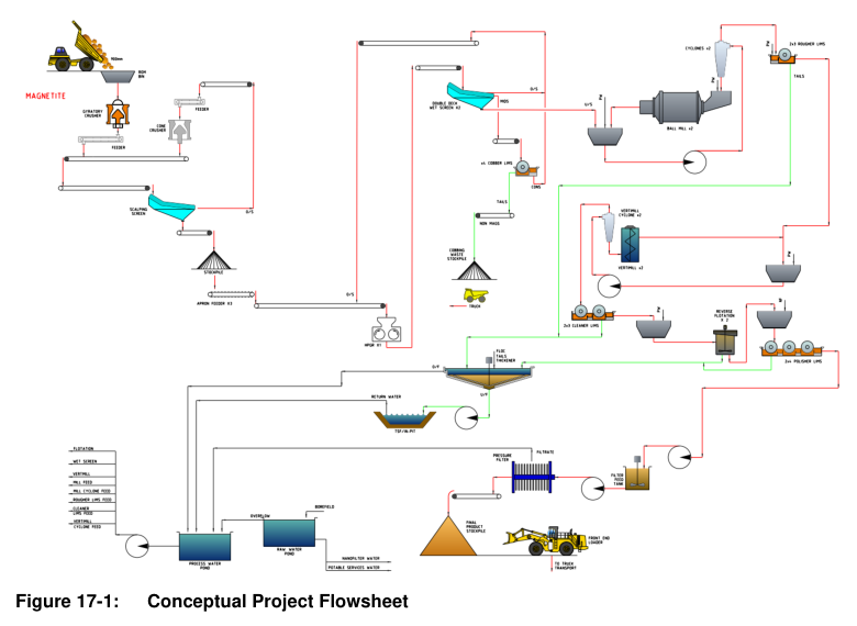
The Lake Giles Iron Project processing route is designed to produce 3.0 dMtpa of magnetite concentrate from approximately 10 Mtpa of feed using a flowsheet comprising conventional crushing, HPGR, magnetic separation, reverse flotation, and pressure filtration.
Report context
This NI 43-101 Technical Report and Feasibility Study for the Lake Giles Iron Project describes a proposed processing facility designed to treat magnetite ore from open cut mining of the Moonshine and Moonshine North deposits at a rate of 9.68 Mtpa. The report presents a conceptual flowsheet and design parameters for the beneficiation plant.
Processing route
Primary Crushing
Ore from the mine is delivered by dump trucks to a 50-inch by 65-inch gyratory crusher with two loading points. A rock breaker installed adjacent to the crusher breaks up oversize rocks in the feed as required. A discharge feeder and conveyor transfer crushed ore to a 447-tonne secondary scalper feed bin. A 20-tonne crane is installed for crusher maintenance.
Secondary Scalping and Crushing
The secondary scalper feed bin discharges via a belt feeder onto a 3.6 m by 8.5 m double-deck scalping screen. Coarse fractions pass to the secondary crusher bin feed conveyor, while minus 40 mm undersize material passes to the HPGR feed stockpile. Oversize material from the scalping screen is fed at a controlled rate to an MP1000 secondary cone crusher under choke-fed conditions. Crusher cavity level monitoring maintains the choke feed arrangement; if the bin level becomes low, feed stops and the crusher coasts until the bin refills. Crushed ore returns to the scalping screen feed conveyor.
HPGR and Dry LIMS
Three under-stockpile apron feeders discharge ore from the HPGR feed stockpile onto the HPGR feed bin conveyor. The bin discharge passes through a metal detector before being choke fed to the HPGR feed chute. A 2.4 m by 1.65 m wide HPGR unit performs size reduction. The HPGR product is wet screened in parallel on two 4.2 m by 8.5 m double-deck screens splitting at 12 mm and 3 mm. The minus 3 mm material passes to a dedicated primary ball mill cyclone cluster. The mid-sized fraction (minus 12 mm, plus 3 mm) is subject to Dry LIMS separation to remove a barren stream and reduce milling requirements. The magnetic fraction from Dry LIMS and the screen oversize recirculate to the HPGR feed conveyor.
Magnetite Processing
The beneficiation plant operates in two parallel streams to minimise the effects of maintenance and breakdowns.
Primary Grinding and Rougher LIMS
Primary milling uses two parallel 6.1 m by 10.2 m EGL ball mills, each fitted with 6,700 kW motors, grinding in closed circuit with dedicated cyclones. Cyclone overflow size is 80% passing 106 microns. This stream feeds 1.2 m diameter by 3.6 m length rougher Wet LIMS units. The rougher stage rejects barren material while maintaining high magnetite recovery. Rougher tails pass to the tailings section. Cyclone underflow returns directly to the ball mill feed.
Secondary Grinding and Cleaner LIMS
Rougher concentrate undergoes further size reduction in two parallel VTM3000WB Vertimills operating in closed circuit with cyclones. Cyclone overflow size is 80% passing 38 microns; underflow returns to the Vertimill. The cyclone overflow feeds the cleaner LIMS stage, consisting of 1.2 m diameter by 3.6 m length double-drum units. Cleaner LIMS tailings flow to the tailings section while concentrate proceeds to reverse flotation.
Reverse Flotation and Polisher LIMS
The flowsheet includes a reverse flotation stage to reduce concentrate silica to an acceptable level. Each reverse flotation bank is fed by a cleaner LIMS unit. The froth layer material is silica rich and is pumped to the tailings section. The reverse flotation concentrate flows from the base of the cell and is subjected to a 1.2 m diameter by 3.6 m length triple-drum polisher LIMS stage. A low-salinity water wash on the final drum reduces alkali metal content in the concentrate. Polisher tails pass through a polishing tank to collect any entrained fine concentrate for intermittent return to the process, before flowing to the tailings section.
Filtration and Stockpiling
Concentrate from the polisher LIMS feeds two parallel 10 m diameter by 10 m high filter feed tanks. Low-salinity water is added to maintain a density suitable for pressure filtration. Each tank feeds one pressure filter, with an additional filter on standby. Filter cake is transferred by conveyor to the plant concentrate stockpile prior to truck loading by front-end loader for transport to the rail siding.
Tailings
The tailings section includes a collection box that feeds a 30 m diameter tailings thickener. Thickened tails are directed to the Tailings Storage Facility for long-term storage.
Key reported parameters
| Parameter | Value | Basis |
|---|---|---|
| Plant feed rate | 10 Mtpa | Design (based on assumed weight recovery) |
| Concentrate production | 3.0 dMtpa | Design |
| Assumed weight recovery | 31% | Design assumption |
| Primary crusher type | 50" × 65" gyratory | Design |
| Secondary crusher type | MP1000 cone | Design |
| HPGR dimensions | 2.4 m × 1.65 m wide | Design |
| Scalping screen | 3.6 m × 8.5 m double deck | Design |
| HPGR wet screens (2 units) | 4.2 m × 8.5 m double deck | Design |
| Primary ball mills (2 units) | 6.1 m × 10.2 m EGL, 6,700 kW each | Design |
| Primary grind size (cyclone overflow) | 80% passing 106 microns | Design |
| Vertimills (2 units) | VTM3000WB | Design |
| Secondary grind size (cyclone overflow) | 80% passing 38 microns | Design |
| Rougher LIMS | 1.2 mD × 3.6 mL | Design |
| Cleaner LIMS | 1.2 mD × 3.6 mL double drum | Design |
| Polisher LIMS | 1.2 mD × 3.6 mL triple drum | Design |
| Filter feed tanks (2 units) | 10 m diameter × 10 m high | Design |
| Tailings thickener | 30 m diameter | Design |
| Secondary scalper feed bin | 447 tonnes | Design |
| Mining rate (Moonshine and Moonshine North deposits) | 9.68 Mtpa | Proposed |
Project website: https://macarthurminerals.com/projects-item/2022-ni43-101-technical-report-a-feasibility-study-lake-giles-iron-project-menzies-western-australia/
Project website: https://macarthurminerals.com/
Technical qualifications
The processing information presented in this report is based on a conceptual flowsheet and design parameters. No historical operating data or testwork results for the Lake Giles Iron Project processing route are provided in the source document. All stated parameters represent proposed design specifications unless otherwise noted.
Source: NI 43-101 Technical Report and Feasibility Study, Lake Giles Iron Project. Section 17: Recovery Methods.
