

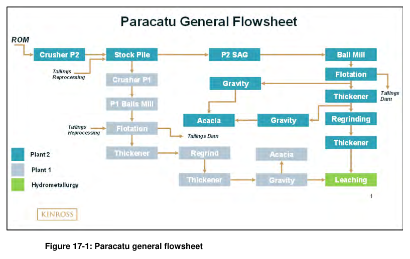
The Paracatu Project operates two processing plants and tailings reprocessing circuits, with infrastructure designed to support a 61 Mt/a operation in Brazil.
Report context
This technical report for the Paracatu Project, dated 2020, describes the processing facilities and recovery methods at the operation in Brazil. The site includes Plant I, operating continuously since 1987, and Plant II, in operation since 2008. Tailings reprocessing commenced in 2015.
Processing route
Plant I
Plant I has operated continuously since 1987 with expansion upgrades in 1997 and 1999. In 2018, the plant processed 8.25 Mt at a Bond Work Index (BWI) of approximately 13.9 kWh/t.
Crushing. The crushing circuit consists of four independent parallel operating lines (A, B, C and D). Each line comprises a primary screen (Metso 8 ft x 20 ft), a primary crusher (APSM Hazemag), a secondary screen (Metso 6 ft x 16 ft) and a secondary crusher (HP300). The lines are fed with front end loaders using material from the Plant II stockpile and pebbles from Plant II. The crushing circuit product has a P80 of 12 mm.
Grinding. The grinding circuit consists of four primary ball mills (4.5 m diameter by 5.7 m long effective grinding length, 1.8 MW gearless drives), one secondary ball mill (5 m diameter by 7.6 m long EGL, 3 MW drive) and one rod mill used to regrind the primary ball mill oversize. The ball mills operate in closed circuit with hydrocyclones (GMAX20). The grinding circuit is operated to produce a product with a particle size distribution with a P80 of 150 microns.
Flotation and regrind. The grinding circuit product (cyclone overflow) feeds the rougher flotation circuit consisting of Wemco cells (10 cells of 42.5 m³ each), Outokumpu cells (4 cells of 16.5 m³ each) and Smartcells (4 cells of 127 m³ each). A portion of the rougher concentrate is fed to a Knelson Concentrator (QS48). The cleaner flotation circuit (Outokumpu cells, 5 cells of 16.5 m³ in operation) receives concentrate from the rougher circuit. Cleaner tails are refed to the rougher flotation feed, while rougher tailings are discharged to the tailings dam.
Cleaner concentrate feeds a dewatering thickener, which subsequently feeds a regrinding circuit consisting of two ball mills (220 kW and 130 kW) operated in closed circuit with hydrocyclones. A portion of the cyclone underflow is treated by a Knelson concentrator (XD30). The regrinding circuit product at a P90 of 45 µm is directed to a dewatering thickener. Dewatered slurry is directed to the Hydro (CIL) circuit for further processing. Concentrates from the Knelson concentrator are processed in an Acacia intensive leaching system. Thickener overflow water returns to the Plant I grinding circuit.
Plant II
Plant II was developed as part of the Paracatu Expansion III Project. The plant consists of one in-pit crusher (MMD toothed roll type), a 1.8 km conveyor to a covered stockpile area, one 20 MW semi-autogenous grinding (SAG) mill and two 13 MW ball mills. A third ball mill (15 MW) was installed in June 2011, and a fourth ball mill (15 MW) was installed in August 2012. In 2018, the plant processed 35.4 Mt of run-of-mine material at a BWI of approximately 13.9 kWh/t.
Crushing and stockpile. The primary crusher is located in the open pit. ROM ore is delivered by haul trucks to the 480 t crusher dump hopper. An apron feeder withdraws ROM ore from the dump hopper and feeds an MMD 1300 Series Twin Shaft Sizer. The MMD sizer crushes rock from a maximum size of 1,300 mm to a nominal size of 350 mm and discharges onto a sacrificial conveyor, which in turn discharges onto the 1.8 km overland conveyor. A stationary hydraulic rock breaker at the MMD sizer feed chamber breaks oversize rock. The MMD sizer can be removed to a maintenance position using a winch and slide rails.
Crushed ore is sent to a covered ore stockpile with a rectangular A frame. Ore is delivered to the stockpile by a tripper conveyor. The stockpile provides 45,000 t of live volume, and the volume can reach 282,000 t when dozers push ore to its borders. The reclaim tunnel has six variable speed belt feeders, a bag house, dust collector and escape tunnel.
Grinding. The Plant II grinding circuit consists of one SAG mill (11.6 m diameter by 6.7 m long EGL, 20 MW gearless drive), two ball mills (7.3 m diameter by 12.0 m long EGL, 13 MW drive) and two ball mills (8 m diameter by 12.8 m long EGL, 15 MW drive). The ball mills are equipped with dual pinion gear drives. The SAG mill operates in open/closed circuit with a trommel screen and vibrating screen. Pebbles have the option to be fed to Plant I (open circuit) or back to the SAG (closed circuit). Oversize rejects from the SAG mill are transferred to the SAG mill feed conveyor by three pebble conveyors in series when operated in closed circuit. When operating in open circuit, the oversize rejects are transferred by conveyor to the Plant I crushing circuit.
SAG mill discharge screen undersize and trommel screen undersize flow to a pump box, from which they are pumped to the ball mill circuits. Each ball mill operates in closed circuit with a set of hydrocyclones. The grinding circuit is operated to obtain a nominal flotation feed particle size distribution with a P80 of 150 µm. Cyclone overflow reports to the flotation circuit, while underflow reports back to the ball mill.
Flotation, gravity and regrinding. The flotation rougher circuit receives fresh feed plus circulating load from cleaner flotation cells. The rougher circuit consists of 24 rougher flotation cells arranged in four rows of six cells each, fed by cyclone overflow from the grinding circuit. The cells are 160 m³ tanks fitted with self-aspirating mechanisms. Reagents (collectors and frother) are supplied from reagent tanks to head tanks in the grinding circuit, with metering pumps adding reagents to the grinding hydrocyclone overflow launder.
First rougher concentrate is processed by three Knelson concentrators (QS48). The rougher concentrate is treated in a cleaner circuit consisting of two rows of five self-aspirated 60 m³ tank cells. Cleaner tailings flow to a pump box and are pumped to the rougher flotation feed distribution box. Cleaner concentrate is collected in a single pump box and pumped to the dewatering thickener. Water from thickener overflow returns to the ball mill discharge boxes. Dewatered concentrate is fed to a vertimill (13.5 m high, 931 kW vertical stirred type) where it is ground to 90% passing 45 microns. The mill operates in closed circuit with ten 254 mm diameter hydrocyclones (GMAX26). A Knelson concentrator (Model XD40) treats the circulating load (underflow) of the vertimill. The vertimill product (hydrocyclone overflow) reports to the dewatering thickener. Dewatered slurry is directed to the Hydro circuit for further processing. Gravity concentrates are transported to the Hydro (CIL) Plant for further processing in an Acacia reactor.
Hydro (CIL) circuit
Hydro receives flotation concentrate from Plant I and Plant II. The typical concentrate gold grade is 10-15 g/t and total sulfur content is 20-25%. The concentrate is fed to an agitated pre-aeration tank where lime is added to adjust pH to approximately 10.5. Pre-aeration residence time is approximately four hours, and CIL residence time is 30-40 hours. The CIL circuit consists of eight tanks with a volume of 750 m³ each.
Oxygen is injected into the pre-aeration tank using a fillblast system to increase the dissolved oxygen concentration to approximately 9-10 mg/L. The slurry flows by gravity through an eight-stage CIL circuit. Cyanide is added into the first CIL tank and adjusted to a concentration of approximately 700-750 mg/L NaCN. The cyanide concentration decreases down the CIL circuit, reaching 150-200 mg/L NaCN in the final tank. The leached slurry passes from CIL 8 into two cyanide treatment tanks (250 m³ each). Tailings slurry is treated for cyanide destruction in an agitated tank using ammonium bisulfite and oxygen.
Carbon elution and regeneration. Loaded carbon is transferred out of CIL twice daily. The loaded carbon is screened and flows by gravity to an acid washing column. Carbon is treated with 5% hydrochloric acid for four hours to remove calcium carbonate deposits and other inorganic contaminants. Spent acid is neutralized with sodium hydroxide before discarding to the tails pump box. From the acid wash vessel (1 column, 14 t capacity, 36 m³), carbon is pumped to the elution columns (2 columns, 14 t capacity, 36 m³). The elution cycle operates with a 0.2% sodium cyanide and 2-3% sodium hydroxide solution at 140°C and 300 kPa for approximately eight hours. After elution, carbon is pumped to the regeneration kilns. Two electrically powered kilns with 600 kg/h capacity each regenerate carbon at 700°C. Regenerated carbon is screened to remove fines before being reintroduced to the CIL circuit.
Intensive cyanidation. Gravity concentrates from the Plant I and Plant II gravity circuits are treated by intensive cyanidation. Plant I gravity concentrate is treated in an Acacia CS2000, while Plant II concentrate is treated in an Acacia CS8000. The pregnant leach solution from the Acacia systems is pumped to the electrowinning circuit. The solids residue from the Acacia system is sampled and pumped to the CIL circuit.
Electrowinning and refining. Pregnant solution from elution is combined with solution from the gravity circuit and is pumped to four electrowinning cells (Summit Valley Model 125 EC33, 3.5 m³ each, sludging cathode type). Periodically, cathodes are cleaned using a high-pressure washer, and gold-bearing sludge is recovered by a filter press. The resulting filter cake is dried, mixed with fluxes (borax, soda ash and occasionally sodium nitrate) and fed to electric induction furnaces. Doré metal and slag separate in the furnace, and the slag is poured off into slag pots. The doré metal is then poured into bars.
Tailings reprocessing (PSAT and PET projects)
In August 2015, Paracatu began the PSAT project, and in mid-2017, the Eustáquio Tailings (PET) project commenced. These projects target gold that has segregated naturally in the tailings basins. Coarser material from PSAT and PET is excavated and hauled by truck to the Plant II stockpile, where the tailings are comingled with ROM to feed the SAG mill. Finer material from PSAT is hydraulically mined using a high-pressure water jet and pumped to the Plant I flotation circuit.
Key reported parameters
| Parameter | Unit | Value | Basis |
|---|---|---|---|
| Site design capacity | Mt/a | 61 | Infrastructure design |
| Plant I 2018 throughput | Mt | 8.25 | Historical operating data |
| Plant II 2018 throughput | Mt | 35.4 | Historical operating data |
| Plant I Bond Work Index | kWh/t | ~13.9 | Historical operating data |
| Plant II Bond Work Index | kWh/t | ~13.9 | Historical operating data |
| Plant I crushing product P80 | mm | 12 | Design specification |
| Plant I grinding product P80 | µm | 150 | Design specification |
| Plant II grinding product P80 | µm | 150 | Design specification |
| Concentrate gold grade | g/t | 10-15 | Typical reported range |
| Concentrate total sulfur | % | 20-25 | Typical reported range |
| CIL residence time | hours | 30-40 | Design specification |
| Pre-aeration residence time | hours | ~4 | Design specification |
| CIL tank volume (each) | m³ | 750 | Design specification |
| NaCN concentration (first CIL tank) | mg/L | 700-750 | Design specification |
| NaCN concentration (final CIL tank) | mg/L | 150-200 | Design specification |
| PSAT cumulative production (2015-2019) | |||
| – Feed | t | 35,958 | Historical operating data |
| – Grade | g/t | 0.344 | Historical operating data |
| – Recovery | % | 66.01 | Historical operating data |
| – Ounces | oz | 268,371 | Historical operating data |
| PET cumulative production (2015-2017) | |||
| – Feed | t | 5,668 | Historical operating data |
| – Grade | g/t | 0.438 | Historical operating data |
| – Recovery | % | Not available | Historical operating data |
| – Ounces | oz | Not available | Historical operating data |
Project website: https://www.kinross.com/news-and-investors/news-releases/press-release-details/2020/Kinross-files-new-Paracatu-technical-report/default.aspx
Technical qualifications
This article is based solely on the original technical report. The report does not provide information on capital or operating costs, economic analysis, mineral resource or reserve estimates, current ownership structure, or project status beyond the reported date. PET recovery and ounce data from 2018 onward are not reported separately and are counted towards overall circuit recovery.
