

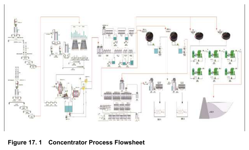
The No. 2 Concentrator Plant at the Jiama Copper Polymetallic Mine in Tibet uses a flowsheet designed for multiple ore types, with separate circuits for copper-lead-zinc and copper-molybdenum ores.
The Jiama Copper Polymetallic Mine is an operating mine located in Tibet, China. The project is owned by China Gold International Resources Corp. Ltd. and operated by Tibet Huatailong Mining Development Co., Ltd. The processing facilities described in this report focus on the No. 2 Concentrator Plant, which is designed to process 12.6 Mtpa of copper-molybdenum ore and copper-lead-zinc ore sourced from both open-pit and underground mining operations.
The report does not state a development status or expected construction timing for this concentrator plant. The information that follows covers the process flowsheet and engineering design basis for the existing facility.
Critical Data
| Parameter | Value | Unit | Notes |
|---|---|---|---|
| Plant name | No. 2 Concentrator Plant | Not applicable | Operated by Tibet Huatailong Mining Development Co., Ltd. |
| Design throughput | 12.6 | Mtpa | Combined copper-molybdenum and copper-lead-zinc ore |
| Crushing feed top size | Less than 300 | mm | Feed to ROM stockpile |
| SAG mill dimensions | Φ10.37 × 5.19 | m | Dual-drive |
| Ball mill dimensions | Φ7.32 × 12.5 | m | Dual-drive overflow |
| Hydrocyclone size | G660 × 10 | Not applicable | Cluster configuration |
| Flotation cell types | KYF-200, KYF-50, XCF-24/KYF-24, XCF-16/KYF-16, XCF-12/KYF-12, XCF-8/KYF-8, XCF-6/KYF-6 | Not applicable | Various sizes for different stages |
| Concentrate thickener type | GZN45 | Not applicable | Copper and copper-lead-zinc |
| Concentrate filter press type | CJZH-18/100/30 | Not applicable | Plate-and-frame filter press |
| Molybdenum filter press type | XMZGE80/1000-U | Not applicable | Plate-and-frame filter press |
| ROM stockpile storage | 124.16 | kt | 64,000 m³ effective volume |
| ROM stockpile duration | 3.1 | days | Not applicable |
| Upstream buffer bin capacity | 1,127 | t | 575 m³ volume |
| Downstream buffer bin capacity | 1,229 | t | 627 m³ volume |
| Lime stockpile capacity | 1,700 | t | 1,400 m³ volume |
| Concentrate storage area | 1,980 and 720 | m² | Two separate areas |
| Concentrate storage duration | 24 and 60 | days | Not applicable |
Overview
The No. 2 Concentrator Plant encompasses the complete mineral processing chain from crushing through final concentrate shipment and tailings disposal. The concentrator process design is based on test work results, evaluation data, trade-off studies, and related design information described elsewhere in the report.
The major processing facilities include crushing, grinding and classification, flotation, concentrate thickening and filtration, and supporting auxiliary facilities.
Key Process Stages
The processing plant uses a single-stage open-circuit crushing process. The crushing system has separate open-pit and underground circuits with identical processing capacities and configurations. For the open-pit circuit, ore is transported by truck to a primary crushing station and fed into a 50-65 hydraulic gyratory crusher. Crushed ore discharges into a surge bin, then a heavy-duty apron feeder withdraws ore onto the open-pit conveyor system. Multiple belt conveyors transport the material to the ROM stockpile feed point.
For the underground circuit, ROM ore is transported by electric locomotives and fed by a vibrating feeder into a 50-65 hydraulic gyratory crusher. Crushed ore enters a surge bin, then a heavy-duty apron feeder withdraws ore onto the underground conveyor system. Multiple belt conveyors transport the ore to the ROM stockpile feed point.
Dust suppression measures have been incorporated into the crushing plant design.
The grinding and classification circuit consists of two parallel processing lines. Each line is dedicated to a different ore type, and both have identical capacities and process configurations. The circuit uses a Semi-Autogenous Grinding plus Pebble Crushing plus Ball Milling configuration, known as an SABC circuit.
Ore is fed from the heavy-duty apron feeder via belt conveyor into a Φ10.37 m × 5.19 m dual-drive SAG mill. Mill discharge passes through a linear vibrating screen. Oversize material goes to a pebble bin and then through an HP500 cone crusher before returning to the SAG mill. Screen undersize combines with discharge from a Φ7.32 m × 12.5 m dual-drive overflow ball mill and flows into a slurry pump sump. The slurry is pumped to a cluster of G660 × 10 hydrocyclones. Cyclone overflow reports to flotation, and cyclone underflow returns to the ball mill for further grinding.
Performance targets for the grinding circuit include SAG mill product at 30% passing 0.074 mm, ball mill product at 50-55% passing 0.074 mm, and hydrocyclone overflow at 70% passing 0.074 mm. These are design targets, not test results.
In the flotation section, the plant operates two independent circuits. Circuit 1 handles copper-lead-zinc bulk flotation. Circuit 2 handles copper-molybdenum bulk flotation followed by copper-molybdenum separation. Final products include copper-lead-zinc bulk concentrate, copper concentrate, and molybdenum concentrate.
The copper-lead-zinc bulk flotation flowsheet has one rougher stage, three scavenger stages, and two cleaner stages. Conditioning uses two Φ8,000 × 8,500 mm high-efficiency mixing tanks. Rougher and scavenger flotation use KYF-200 flotation cells arranged as 6 rougher cells and three groups of 2 scavenger cells. The two cleaner stages use KYF-50 flotation cells arranged as two groups of 3 cleaner cells. All middlings are returned via froth pumps.
The copper-molybdenum bulk flotation flowsheet has one rougher stage, three scavenger stages, and three cleaner stages. Conditioning uses two Φ8,000 × 8,500 mm high-efficiency mixing tanks. Rougher and scavenger flotation use KYF-200 flotation cells arranged as 6 rougher cells and three groups of 2 scavenger cells. The three cleaner stages use KYF-50 flotation cells arranged as two groups of 3 cleaner cells and one group of 2 cleaner cells. All middlings are returned via froth pumps.
The copper-molybdenum separation circuit has one rougher stage, two scavenger stages, and five cleaner stages. Rougher and scavenger flotation use XCF-24/KYF-24 flotation cells arranged as 2 rougher cells and two groups of 2 scavenger cells. Cleaner stages use XCF-16/KYF-16, XCF-12/KYF-12, XCF-8/KYF-8, XCF-8/KYF-8, and XCF-6/KYF-6 cells in a 2+2+2+2+2 configuration. Scavenger tailings constitute the final copper concentrate. The fifth cleaner concentrate constitutes the final molybdenum concentrate.
For dewatering, copper-lead-zinc bulk concentrate is thickened in a GZN45 thickener and filtered using a CJZH-18/100/30 plate-and-frame filter press. Final concentrate moisture is maintained below 12%, and the concentrate is bagged for sale. Copper concentrate follows the same process with the same equipment and moisture target.
Molybdenum concentrate is stored in agitated tanks and dewatered using an XMZGE80/1000-U plate-and-frame filter press. Overflow from the agitation tanks and filtrate from the filter press are directed to a ZXN200 inclined-plate thickener. Settled molybdenum concentrate recovered in the thickener is returned to the filter press, reducing molybdenum losses.
Additional Interesting Data and Summary
The ROM stockpile has an effective storage volume of 64,000 m³ with an ore storage capacity of 124.16 kt and a storage duration of 3.1 days. Buffer ore bins installed upstream and downstream of the rock crusher accommodate choke-fed rock crushing operation and balance the different operating schedules between crushing and grinding. The upstream bin has a volume of 575 m³ and capacity of 1,127 t with a retention time of 2.2 hours. The downstream bin has a volume of 627 m³ and capacity of 1,229 t with a retention time of 2.4 hours.
Bagged concentrate storage areas are located within the concentrate dewatering facility. Two storage areas measure 1,980 m² and 720 m². Their corresponding storage durations are approximately 24 days and approximately 60 days.
A covered quicklime storage yard ensures continuous operation. A small lime surge bin is installed upstream of the ball mill for process control. The lime stockpile holds 1,400 m³ or 1,700 t with a 17.5-day storage duration. The lime bin holds 42 m³ or 50 t with a 0.6-day storage duration.
All flotation reagents are purchased externally and delivered to site in drums by truck. Reagents requiring preparation are stored in the reagent preparation building and lifted by crane to mixing tanks, where water is added to achieve the required concentration. Prepared reagents are pumped to reagent storage tanks equipped with level sensors that automatically control pump operation. Reagents not requiring preparation are lifted directly to the reagent storage tank platform and manually transferred into storage tanks.
All process areas are equipped with maintenance cranes for routine servicing. Maintenance lifting equipment is installed in the crushing plant, screening plant, grinding plant, flotation plant, and concentrate dewatering and drying plant. Adequate maintenance access and working areas are incorporated into the facility layout. Belt conveyors are equipped with 1-5 t electric hoists to facilitate maintenance activities. Major plant overhauls are outsourced to specialized contractors.
A dedicated grinding media storage facility ensures uninterrupted ball consumption requirements. Grinding balls are transferred by crane to ball addition hoppers located at the mill feed end. Electromagnetic metal detectors are installed above conveyor belts upstream of the rock crushing equipment to remove tramp iron and prevent equipment damage.
Flotation air is supplied by dedicated blowers. Due to elevated noise levels, the blower installation is housed in a separate blower building adjacent to the flotation area. Wastewater from all plant areas is collected and routed to centralized treatment facilities to prevent uncontrolled discharge and maintain plant hygiene. Each operating area contains isolated operator rooms and instrument and control rooms to provide a safe and comfortable working environment.
The plant is designed with adequate ventilation throughout, including dedicated dust collection and ventilation systems in dust-generating areas. The overall safety design follows applicable national occupational health and safety regulations and adheres to the principle of Safety First. All operating platforms exceeding 0.6 m in height are equipped with guardrails or protective barriers. Warning signs are installed in hazardous areas throughout the plant to ensure personnel safety.
Key Processes
- Single-stage open-circuit crushing using 50-65 hydraulic gyratory crushers for both open-pit and underground ore sources
- SABC grinding circuit comprising a Φ10.37 m × 5.19 m dual-drive SAG mill, HP500 cone pebble crusher, and Φ7.32 m × 12.5 m dual-drive overflow ball mill
- Hydrocyclone classification using G660 × 10 cluster with overflow targeted at 70% passing 0.074 mm
- Copper-lead-zinc bulk flotation using KYF-200 rougher and scavenger cells and KYF-50 cleaner cells
- Copper-molybdenum bulk flotation using KYF-200 rougher and scavenger cells and KYF-50 cleaner cells
- Copper-molybdenum separation using XCF-24/KYF-24 rougher and scavenger cells with five stages of XCF/KYF cleaner cells
- Concentrate dewatering using GZN45 thickeners and CJZH-18/100/30 plate-and-frame filter presses for copper and copper-lead-zinc concentrates
- Molybdenum concentrate dewatering using XMZGE80/1000-U plate-and-frame filter press with ZXN200 inclined-plate thickener for recovery of settled solids
- Auxiliary systems including ROM stockpile, buffer ore bins, lime milk preparation, reagent facilities, maintenance facilities, grinding media storage, and tramp iron detection
Source: NI 43-101 Technical Report Jiama Copper Polymetallic Mine Mineral Resource and Reserve Update, June 30, 2026. Project website: Jiama Copper Polymetallic Mine
