

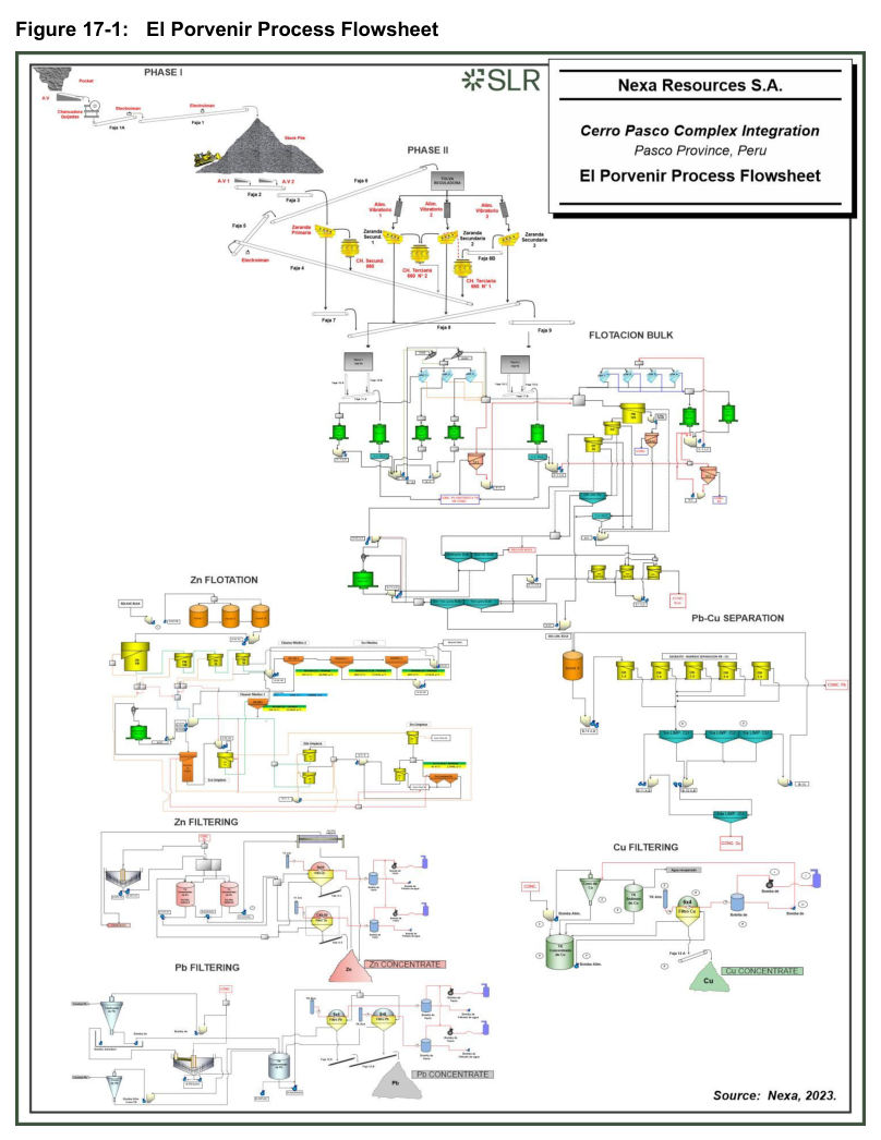
This report describes the existing processing facilities at El Porvenir and Atacocha concentrators that form part of the Cerro Pasco Complex Integration.
Report context
This technical report is dated March 27, 2024, and covers the Cerro Pasco Complex Integration project for Nexa Resources S.A. The processing methods described herein are for the El Porvenir and Atacocha concentrators, which treat ore from the Cerro Pasco district in Peru. The report presents historical operating data, existing plant configurations, and testwork results where applicable.
Processing route
El Porvenir Concentrator
Overview and Capacity
The El Porvenir concentrator has an ore processing capacity of approximately 6,500 tpd (2.37 Mtpa) and consists of conventional crushing, grinding, and flotation to produce copper, lead, and zinc concentrates. The mineralogy is primarily sphalerite, galena, and chalcopyrite, with associated pyrite, pyrrhotite, and limonite. Approximately 35% of the concentrator tailings are used for hydraulic backfill, with the remainder pumped to the tailings storage facility.
Crushing Circuit
Primary crushing takes place underground using a Hewitt Robins 30 in. x 42 in. jaw crusher. The product, with a top size of approximately 4.0 in. to 4.5 in. (100 mm to 125 mm), is transported by conveyor to a 30,000 t coarse ore stockpile at surface. Ore is reclaimed by two reciprocating feeders and transferred to a Metso primary double deck screen. Oversize from both decks reports to a Sandvik 600 secondary cone crusher, while bottom deck screen undersize (P95 9.5 mm) reports to two 1,500 t grinding circuit feed bins. Secondary crusher product with a top size of 30 mm is conveyed to a three-way splitter that distributes material to two Allis Chalmers 6 ft x 16 ft and one Metso 8 ft x 16 ft secondary double deck screens. Oversize from secondary screens feeds two Sandvik CH 660 tertiary crushers, while bottom deck screen undersize (P95 9.5 mm) reports to the grinding circuit feed bins. Tertiary crusher product is returned to the secondary screens, closing the tertiary crushing circuit.
Grinding Circuit
The grinding circuit consists of two Koppers 9.5 ft dia. x 12 ft primary ball mills and five secondary ball mills. Crushed ore with a P95 of 9.5 mm is fed from two grinding circuit feed bins to the primary ball mills. Primary Mill 1 works with three secondary mills: an 8 ft x 4 ft Hardinge mill, an 8 ft x 4 ft Comesa mill, and a 6 ft x 7 ft Comesa mill. The discharge of Primary Mill 1 flows to two Sub A 1500 unit flotation cells. Lead concentrate produced flows to final lead concentrate storage, and cell tailings flow into the secondary ball mill discharge pump box. Part of the slurry is pumped to a hydrocyclone classifier and the remainder to high frequency Derrik vibrating screen feed distributor. Cyclone underflow discharges into the Derrick screen distributor along with secondary ball mill discharge slurry and is fed to the high frequency Derrik screens. Coarse material from the Derrik screens feeds the secondary ball mills, while fine screen undersize and cyclone overflow are combined, with a portion directed to an SK1 flash flotation cell. The secondary ball mill discharge slurry is pumped to the Derrick screens, closing the circuit. Primary Mill 2 works with two secondary mills: a Comesa 8 ft x 10 ft mill and an 8 ft x 5 ft Hardinge mill. The discharge of Primary Mill 2 goes to two Sub A 1500 unit cells, with lead concentrate reporting to final concentrate and flotation tailings pumped to a second bank of high frequency Derrick screens. Screen undersize is pumped to the flotation circuit and screen oversize flows to Secondary Mills 4 and 5. The discharge of Secondary Mill 4 goes to an SK240 cell, with lead concentrate reporting to final concentrate and flotation cell tailings combined in the secondary ball mill discharge sump and pumped to the Derrick screens for classification, closing the grinding circuit. The addition of Secondary Mills 4 and 5 and optimizations of the milling circuit contributed to the increase in tonnage from 5,800 tpd to 6,500 tpd.
Daily ball charge mixture to primary mills is 2.5 in. (20%) and 3 in. (80%) sizes, while secondary milling uses 1.5 in. and 2 in. ball sizes. Steel consumption in the ball mills is 0.380 kg/t. The required product granulometry is 12% plus 70 mesh (210 µm) and 52% minus 200 mesh (74 µm).
Bulk Flotation
The bulk flotation circuit consists of bulk rougher, scavenger, and cleaner cells and produces a copper and lead concentrate. Bulk scavenger concentrate is reground before being returned to the roughers. Bulk flotation is followed by copper-lead separation consisting of copper roughers, scavengers, and cleaners, during which copper minerals are floated while lead minerals are depressed to produce separate copper and lead concentrates. Tailings from the bulk flotation circuit feed the zinc flotation circuit. The first rougher is an FM-100 cell, the second rougher is an OK-30, the third rougher is an OK-50 cell, the first scavenger is made up of two DR-300 cells, the second scavenger of six DR-100 cells, and the third scavenger of six DR-100 cells. Zinc sulphate and sodium cyanide are used as depressants of zinc and iron minerals. Xanthate Z-11, Aerphine-3418, and methyl isobutyl carbinol (MIBC) are used as collectors of lead minerals in the unit cells located in the discharges of the primary mills. Xanthate Z-11 is the main collector and Aerophine-3418 is the secondary collector used in bulk Cu-Pb-Ag flotation. The pH ranges from 7.5 to 11.5.
Lead-Copper Separation
Concentrates from the third bulk cleaner circuit enter the lead copper separation circuit. The bulk concentrates pass through five OK-1.5 copper rougher cells. The tailings are the lead concentrate, and the concentrate is the copper concentrate. The copper concentrate passes through two stages of cleaning before the final copper concentrate is produced. Reagents used for separation are MIBC and a mixture of carboxymethyl cellulose (CMC), sodium silicate, and sodium bichromate.
Zinc Flotation
Tailings from the bulk flotation circuit undergo three stages of conditioning prior to zinc flotation. The zinc flotation circuit consists of zinc roughers, scavengers, and three stages of cleaning to produce zinc concentrate and final tails. Lime is used as a pH modifier (9.5-11.5), copper sulphate as a reactivator of zinc minerals, xanthate as the main collector, and Flottec-4234 as secondary collectors. MIBC is the only frother. The circuit consists of two OK-100 cells as the first and second roughers and one OK-50 as the third rougher, with an OK-30 for the first scavenger. The medium cleaner circuit includes an OK-20, five DR-300 cells, eight DR-100 cells as cleaner scavengers, and eight DR-100 cells as second cleaner scavengers. The first cleaner is a column cell that works with the concentrate of the first and second rougher. The second cleaners consist of two OK-10 cells, and the third cleaners have an OK-5 cell and five DR-24 cells.
Concentrate Dewatering
Concentrates are dewatered in thickeners (lead and zinc) and a dewatering cone (copper) followed by a filter press for zinc concentrate and disc filters for lead and copper concentrates. Filtered concentrates are stored in covered stockpiles prior to truck loading. Lead and zinc concentrate moisture content is approximately 8% to 9%, and copper concentrate moisture content is approximately 11%. Water from machinery cooling is recovered at approximately 20.5 L/s in the dry season. Water is also recovered from filtration operations and the wastewater treatment plant for use in the hydraulic backfill plant.
Tailings System
Tailings at approximately 22% solids are classified in cyclones. Coarse material in the underflow at approximately 62% solids is sent to the hydraulic backfill plant for use in the mine as backfill. Mine backfill constitutes approximately 50% of tailings produced. Water from tailings dewatering is returned to the process. Overflow from the cyclones containing the fine tailings is deposited in the conventional tailings storage facility adjacent to the mine and processing plant.
Atacocha Concentrator
History and Overview
Minera Atacocha was founded on February 8, 1936. The first concentrator (Plant No. 1) began operations in 1937 with a treatment capacity of 100 tpd for lead ore beneficiation by flotation. Lead-zinc extraction by differential flotation has been conducted since 1941. Plant No. 1 operated for thirty years, ending operations in 1968 with a capacity of 200 tpd. Plant No. 2 began operations in 1950 with an initial capacity of 375 tpd and was expanded to 1,500 tpd in 1968. Concentrator No. 2 gradually increased treatment tonnage, reaching 3,750 tpd in 2007 due to process improvements. In November 2008, the tertiary crusher was replaced by a Nordberg HP500, improving crushing product granulometry and increasing production rate to 4,380 tpd. By November 2016, the P80 of the crushed product was reduced to 5,000 µm and by January 2017, the production rate increased to 4,600 tpd. Concentrator No. 2 currently treats an average of 4,400 tpd of ore producing lead concentrate (48% to 55% Pb) and zinc concentrate (48% to 55% Zn).
By 2019, Atacocha underground reserves were nearly depleted, and the plant began treating ore from the San Gerardo open pit mine. The amount of San Gerardo ore treated progressively increased through May 2020, after which all ore supplied was from the open pit. The open pit ore characteristics differed from Atacocha underground ore, so the production rate was restricted to 4,100 tpd. Copper head grades from the open pit were too low to make saleable concentrate grade, so copper concentrate production was discontinued, leaving only lead and zinc concentrate products. The operational process was optimized to resume treatment of 4,400 tpd at the end of 2023.
Mineralogy
Mineralization in the Atacocha area consists primarily of veins and bodies of massive galena, black sphalerite, and cubic pyrite, emplaced in green garnet skarn zones, breccia marble, and in contact with siliceous breccias. In the Santa Bárbara area, the recurrent mineral is argentiferous galena with a lower proportion of blond sphalerite and fine pyrite, mainly located in calcareous breccias. Mineralization at San Gerardo consists of narrow veins of massive galena, blond sphalerite, freibergite, and fine pyrite, emplaced in brecciated carbonate rocks and dacitic intrusive rocks. Gold is found as structural impurities in all sulphides, economic and non-economic, including alabandite.
Crushing Circuit
Mined ore is stored in four coarse underground hoppers located at the 3600 Level. Hopper No. 1 has a capacity of 1,600 t, Hopper No. 2 has a capacity of 1,900 t, Hopper No. 3 has a capacity of 800 t, and Hopper No. 5 has a capacity of 700 t. Ore is fed to the crushing section by conveyor. Hoppers No. 1 and No. 2 each work with a 42 in. x 12 ft Comesa apron feeder; Hoppers No. 3 and No. 5 each work with 60 in. x 16 ft Comesa apron feeders. Ore is conveyed to a 1,100 mm x 850 mm Nordberg C110 B primary jaw crusher. Crusher product is conveyed to a primary Simplicity double deck screen. Screen undersize is conveyed to fine ore storage bins. Upper deck screen oversize feeds a secondary Sandvik CH660 cone crusher. Lower deck screen oversize discharges onto belt No. 4, which joins with the secondary crusher product, and both are conveyed to a secondary 8 ft x 20 ft double deck banana type screen. Secondary banana screen bottom deck (3/8 in.) undersize reports to fine ore storage bins, and oversize from both decks feeds a tertiary Nordberg HP-500 cone crusher. Tertiary crusher product is conveyed to a tertiary Simplicity screen. Tertiary screen undersize reports to fine ore bins, and screen oversize from both decks feeds the tertiary crusher, closing the circuit. Product conveyor No. 9 distributes ore to each of six 450 t fine ore bins using a tripper conveyor.
Grinding Circuit
The grinding circuit comprises six ball mills: two Hardinge 8 ft x 5 ft conical mills and four Comesa 8 ft x 10 ft mills as primary mills, and one Hardinge 8 ft x 5 ft conical ball mill used as a secondary mill. Five of the primary mills operate in closed circuit. The discharge of each mill is fed to an SK-80 flash flotation cell that recovers coarse lead concentrate which is pumped directly to lead concentrate storage. Tailings from these cells are pumped to a 15 in. hydrocyclone classifier. Cyclone underflow feeds the primary ball mill, and hydrocyclone overflow feeds a 10 ft dia. by 12 ft high lead-copper flotation conditioner. The sixth primary mill operates in series with a secondary mill. The primary mill discharge feeds an SK-80 flash flotation cell. SK-80 tailings are pumped to a 15 in. hydrocyclone. Cyclone underflow feeds the single secondary ball mill, which is closed by a 20 in. hydrocyclone. Each primary mill is fed by variable speed conveyor belts, and tonnage is automatically controlled by Ramsey scales. Zinc sulphate (depressant) and sodium cyanide (depressant) are added to each primary mill, and xanthate (Z11 or Z14) and MIBC are added to each flash flotation cell.
Flotation Circuit
The flotation plant consists of three circuits controlled by a Courier 6SL inline analyzer installed in September 2004 (currently only the multiplexer operates). The bulk rougher circuit produces a bulk copper-lead concentrate that is then separated in the lead circuit to produce copper and lead concentrates. The zinc circuit processes tailings from the copper and lead circuits, including a regrinding stage, to produce zinc concentrate and final tails.
The bulk rougher flotation circuit treats the whole ore, obtaining lead concentrates made up of concentrates from the grinding circuit SK-80 flash flotation cells plus OK-8 and OK-20 cleaner concentrates and OK-30 I and 1st OK-8 scavenger concentrates. To this are added concentrates of the RCS-30 and 2nd plus 3rd OK-8 scavenger cells. Cleaner tailings are recycled to the bulk rougher feed. Feed to the cleaners is made up of rougher concentrates. Concentrates from the OK-30 I cells are fed to OK-3 cells (lead cleaning), with concentrate from these cells also forming the lead concentrate and tailings returning to the rougher feed.
Tailings from the bulk rougher OK-30 II cells feed the bulk scavenger flotation circuit consisting of an OK-20 cell followed by a bank of six OK-8 cells and one OK-16 cell. The OK-20 scavenger concentrate flows to a bank of five cleaner scavenger OK-8 cells. Bulk scavenger tailings feed the zinc circuit.
Since July 2019, no Pb/Cu separation has been carried out due to a copper head grade of less than 0.10%, ranging from 0.06% to 0.08%. Pb/Cu separation can be resumed when the copper head grade improves.
The zinc rougher circuit processes tailings from the bulk lead-copper scavenger circuit with conditioning in two 16 ft dia. x 16 ft agitated tanks operated in series. The zinc rougher circuit consists of one OK-100 cell and one OK-50 cell operated in series. The scavenger circuit consists of a bank of three OK-16 cells, a bank of four OK-16 cells, and one OK-50 cell. The cleaning circuit consists of one stage using an OK-10 cell and a bank of five OK-3 cells. Zinc scavenger tailings are final tailings. The first rougher concentrate and the cleaner concentrate are the final zinc concentrates. Scavenger concentrates return to the second scavenger feed (OK-16), and tailings from the first scavenger are recycled to the second rougher feed.
Flotation Reagents
The main collector is sodium isopropyl xanthate (Z11) at 2.2% solution for rougher-scavenger stages, bulk lead-zinc, and zinc stages. MIBC is used as frother for both lead and zinc circuits and is added neat. Depressants include sodium cyanide (1% solution) and zinc sulphate (3.30% solution) added in milling. Copper sulphate (4.50% solution) is used as zinc activator in the zinc circuit. Hydrated lime Ca(OH)2 powder (65% CaO) is added for pH control in the zinc circuit.
Concentrate Dewatering
Lead and zinc flotation concentrates are pumped to two parallel concentrate thickeners for each metal for dewatering. Thickener underflow slurry from lead and zinc thickeners is pumped to lead and zinc concentrate storage tanks respectively for density control. Slurry is then pumped to a CC-45 ceramic disc filter, which reduces moisture in each concentrate to approximately 8.2% for transportation. Filter aid at 20 g/t is added to improve filtration. Two drum filters can be used for either lead or copper concentrate dewatering. Filtered concentrates are discharged to concentrate storage areas for shipping.
Tailings Pumping System
Atacocha's tailings transport system is a high pressure pumping system using Geho positive displacement pumps designed to pump thickened tailings at a density of 55% to 65% solids to the Atacocha tailings dam. A project is being developed for a treatment rate of 5,000 dry tpd, representing 4,500 tpd of tailings. General tailings are fed to a 125 ft thickener at a density of 1,250 g/L to reduce total volume. Flocculant is dosed at 30 L/min at a concentration of 0.025%. Thickener underflow is recirculated with HR-200 pumps until it reaches 55% to 65% solids. When the pulp reaches appropriate density, it is fed into a linear sieve to store clean pulp of adequate granulometry in storage tanks. When density decreases, pulp is recirculated to the thickener until adequate density is again achieved. Overflow with less than 50 ppm solids is stored in a tank and recirculated to the concentrator, with excess water sent to settling ponds.
Key reported parameters
| Parameter | Unit | Design Value | Historical Operating Data | Testwork Basis |
|---|---|---|---|---|
| El Porvenir ore processing capacity | tpd | 6,500 | Increased from 5,800 to 6,500 (historical) | Not reported |
| El Porvenir ore processing capacity | Mtpa | 2.37 | Not reported | Not reported |
| El Porvenir primary crusher product top size | in. (mm) | 4.0–4.5 (100–125) | Not reported | Not reported |
| El Porvenir screen undersize (crushing) | mm (P95) | 9.5 | Not reported | Not reported |
| El Porvenir steel consumption (ball mills) | kg/t | Not reported | 0.380 | Not reported |
| El Porvenir product granulometry (plus 70 mesh) | % | Not reported | 12 | Not reported |
| El Porvenir product granulometry (minus 200 mesh) | % | Not reported | 52 | Not reported |
| El Porvenir lead concentrate moisture | % | Not reported | 8–9 | Not reported |
| El Porvenir zinc concentrate moisture | % | Not reported | 8–9 | Not reported |
| El Porvenir copper concentrate moisture | % | Not reported | 11 | Not reported |
| El Porvenir water recovery (machinery cooling) | L/s | Not reported | 20.5 (dry season) | Not reported |
| El Porvenir tailings for backfill | % | Not reported | 35 | Not reported |
| El Porvenir mine backfill from tailings | % | Not reported | 50 | Not reported |
| Atacocha ore processing capacity | tpd | 4,400 | Historical: 100 (1937), 200 (1968), 375 (1950), 1,500 (1968), 3,750 (2007), 4,380 (2008), 4,600 (2017), 4,100 (open pit restriction) | Not reported |
| Atacocha ore processing capacity | Mtpa | 1.68 | Not reported | Not reported |
| Atacocha crushed product P80 | µm | Not reported | 5,000 (November 2016) | Not reported |
| Atacocha lead concentrate grade | % Pb | Not reported | 48–55 | Not reported |
| Atacocha zinc concentrate grade | % Zn | Not reported | 48–55 | Not reported |
| Atacocha copper head grade (post-2019) | % Cu | Not reported | 0.06–0.08 | Not reported |
| Atacocha concentrate moisture (ceramic disc filter) | % | Not reported | 8.2 | Not reported |
| Atacocha filter aid consumption | g/t | Not reported | 20 | Not reported |
| Atacocha water consumption | m³/t concentrate | Not reported | 2 | Not reported |
| Atacocha power consumption | kWh/t | Not reported | 32.5–33 | Not reported |
| Atacocha tailings transport density | % solids | 55–65 | Not reported | Not reported |
| Atacocha thickener feed density | g/L | Not reported | 1,250 | Not reported |
| Atacocha flocculant dosage | L/min | Not reported | 30 | Not reported |
| Atacocha flocculant concentration | % | Not reported | 0.025 | Not reported |
| Atacocha thickener overflow solids | ppm | Not reported | <50 | Not reported |
Project website: https://www.newsfilecorp.com/release/262261/Nexa-Provides-Operational-Update-on-Cerro-Pasco-Complex
Atacocha Flotation Reagent Consumptions (Historical Operating Data)
| Reagent | Consumption (g/t) |
|---|---|
| Nitric acid | 17 |
| Hydrated lime, mill | 10 |
| Sodium cyanide | 22 |
| Methyl isobutyl carbinol, MIBC | Not stated |
