

This report details the proposed processing route for the Idaho Cobalt Project, comprising a concentrator and a cobalt production facility, based on design criteria.
Report context
The NI 43-101 Technical Report for the Idaho Cobalt Project documents the designed processing methods and recovery criteria for a mineral processing operation. The concentrator is a typical froth flotation recovery plant that has had all major pieces of equipment procured and ready for installation. The processing route includes two stages of crushing, one stage of grinding, a rougher/cleaner flotation circuit, followed by a cobalt production facility (CPF) for further refining. The report provides basic design criteria and planned process flowsheets for both the concentrator and the CPF.
Processing route
Concentrator
ROM mineralized material is delivered via truck from the mine portal to a coarse stockpile with a live storage capacity of 800 tons, sufficient for one full operating day.
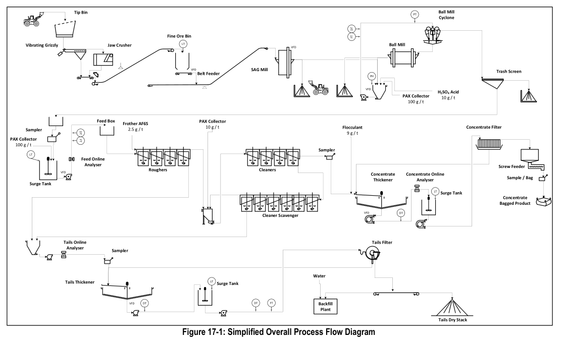
Crushing, screening and storage. Primary crushing is performed by a jaw crusher and secondary crushing by a standard cone crusher. The crushing circuit is designed to produce sufficient feed in one 12-hour shift per day. A grizzly feeder reclaims material from the feed hopper; undersize bypasses the primary crusher while oversize discharges into the jaw crusher. The primary crushing product has a nominal P80 of 2.5 inches. Material then feeds a triple-deck vibrating screen; oversize discharges into the cone crusher which operates in closed circuit with the screen. The final crushing circuit product has a nominal P80 of 3/8 inch. Undersize from the vibrating screen is conveyed to a crushed storage bin and subsequently fed to the ball mill. Dust collectors are provided in the crusher and storage areas.
Grinding. Crushed mineralized material, process water and potassium amyl xanthate (PAX) are fed to the ball mill, which operates in closed circuit with hydrocyclones. Slurry discharges through a trommel screen into a pumpbox and is transferred to a cyclopac for classification. Cyclone overflow is the grinding circuit product; underflow is returned to the ball mill for further grinding.
Flotation. The flotation circuit consists of a conditioning tank, rougher flotation and cleaner flotation. Cyclone overflow flows into the rougher conditioning tank where additional PAX is added. Conditioned slurry is pumped to a distribution box feeding three banks of rougher flotation cells operated in parallel. Rougher flotation tailings are the final tailings from the concentrator. Rougher concentrate is pumped to the cleaner flotation distribution box feeding one bank of cleaner flotation cells. Cleaner tailings are returned to the rougher circuit or, if metal concentrations are sufficiently low, can be pumped directly to the tailings thickener. Cleaner concentrate is the final flotation product and is pumped to the concentrate thickener.
Concentrate and tailings thickening. A final concentrate thickener provides initial dewatering of flotation concentrate, with flocculant added. Thickener overflow water is transferred to a process water tank for reuse. Thickened concentrate is pumped to a concentrate stock tank then dewatered in a concentrate filter press before trucking to the CPF. Tailings from flotation are pumped to a tailings thickener; underflow is pumped to a tailings feed tank prior to final dewatering in a tailings filter press. Filtered tailings are utilized in the mine backfill system.
Concentrator reagents. Reagent mix systems are provided for flocculant, PAX and lime. Two flocculant mix systems are included: one for the concentrate and tailings thickeners, and one for the water treatment plant. Frother system includes a stock tank and metering pumps.
Cobalt Production Facility (CPF)
Concentrate repulp. Concentrate trucked from the concentrator is transferred to a repulp pit and mixed with poor process water to a slurry density of 50 percent solids, then pumped to a regrind mill. A regrind mill feed tank provides surge capacity. The regrind mill further reduces the size of the concentrate. Slurry discharges across a trash screen and is classified using a regrind cyclone. Reground concentrate is pumped to the differential flotation circuit.
Copper scalp flotation. Feed from the regrind circuit enters column flotation where a copper concentrate is produced. Frother and promoter are added to selectively target copper bearing minerals while leaving cobalt minerals in the tailings. Copper concentrate is filtered using a vacuum disk filter and bagged for shipment. Tailings discharge to a surge tank feeding the Copper/Iron Leach circuit.
Metathesis (Copper/Iron Removal Leach). Tailings from copper scalp flotation and raffinate from copper solvent extraction are fed to four agitated closed top tanks. pH in the first two tanks is raised using slaked magnesium hydroxide to precipitate copper; pH in the third and fourth tanks is raised to precipitate iron. Slurry discharges to a copper/iron removal thickener with flocculant addition. Overflow is sent to polishing filters feeding the cobalt solvent extraction circuit. Underflow is pumped to the concentrate feed tank feeding the nitrogen species catalyzed (NSC) pressure oxidation circuit.
Nitrogen species catalyzed pressure oxidation. Thickener underflow from the metathesis circuit is combined with solution from the neutralization thickener belt filter in an agitated tank. Slurry is discharged into the autoclave feed tank and combined with cobalt solvent extraction raffinate, nitric acid and filtrate from the pregnant leach solution (PLS) cooling and filtration circuit. Oxidative conditions within the autoclave are created by oxygen and nitrogen oxide catalysts in aqueous slurry. Minor quantities of catalyst report to flashed vapor, which is scrubbed. Inert gases and nitrogen oxide species are bled from the vapor phase and scrubbed in a series of scrubbers that recover catalyst for recycle.
Catalyst recovery circuit. Flash vapor from the autoclave slurry discharge is directed to the leach flash scrubber. Gases from the autoclave controlled vent and emergency pressure relief system also feed into this scrubber. The scrubber removes entrained slurry so that hot vapor can be employed as a heating medium.
Leach flash cooling and partial neutralization and thickening. Slurry is discharged from the autoclave and allowed to flash in the leach autoclave flash tank. Underflow flows through a series of agitated vessels in series: copper raffinate and flash tank underflow are blended to partially neutralize acid; slaked magnesium hydroxide slurry is added for complete neutralization; flocculant is added in a third flocculation tank. The neutralization thickener provides solid-liquid separation. Thickener underflow is filtered, with solids sent to the gold leach circuit; filtrate is split between the copper solvent extraction feed tank and the concentrate feed tank. Thickener overflow is discharged to a cooling and polishing filtration circuit feeding copper solvent extraction.
Copper solvent extraction. Filtered solution from PLS cooling and filtration and from the neutralization filter is pumped to the copper SX feed tank and then to a series of mixer settlers. Copper is loaded onto organic in a first series of mixer settlers. Lean strip liquor from the copper crystallizer, mixed with sulfuric acid and deionized water, strips metals from organic in a second set of mixer settlers. Barren organic is fed back to the first set. Raffinate is distributed to the copper removal circuit; rich strip liquor is sent to the copper sulfate crystallizer.
Copper sulfate crystallizer. Rich strip liquor from copper SX is fed to a Draft Tube Baffle (DTB) crystallizer. Copper sulfate crystals are harvested, dried, bagged and shipped. It is noted that with modifications, copper electrowinning could be added.
Gold recovery. Filtered solids from the neutralization belt filter are repulped and fed to a carbon in leach (CIL) circuit consisting of agitated tanks. Sodium cyanide solution and slaked magnesium hydroxide are added; gold is leached and absorbed onto carbon flowing counter-current to slurry. Loaded carbon is removed from the first tank, bagged and shipped for refining. Tailings are filtered and shipped off site for disposal; filtrate is returned to the repulp tank.
Cobalt solvent extraction. Filtered solution from copper/iron removal polishing filters is pumped to the cobalt SX feed tank where it is mixed with sulfuric acid and cobalt precipitation filtercake. Pregnant solution is pumped to a series of mixer settlers. Cobalt is loaded onto organic in a first series; lean strip solution mixed with sulfuric acid and deionized water strips metals in a second set. Barren organic is fed back to the first set. Raffinate is distributed to the cobalt precipitation circuit and autoclave feed tank. Rich strip liquor is sent to the cobalt sulfate crystallizer.
Cobalt sulfate crystallizer. Rich strip liquor from cobalt SX is fed to a surfaced cooled crystallizer or DTB crystallizer; further testwork is noted as needed to confirm the crystallizer type. Cobalt sulfate crystals are harvested, dried, bagged and shipped. With modifications, cobalt electrowinning could be added.
Cobalt precipitation. Cobalt is precipitated from cobalt SX raffinate using slaked magnesium hydroxide to form cobalt hydroxy sulfate. The slurry is filtered; filtercake advances to the cobalt SX feed tank and filtrate reports to nickel/zinc precipitation.
Nickel/zinc precipitation. Nickel and zinc are precipitated from cobalt SX raffinate using slaked magnesium hydroxide. The nickel/zinc hydroxide slurry is filtered; product is anticipated to be bagged and sent to market. Magnesium rich filtrate advances to the magnesium sulfate crystallizer. The report notes that capital cost for this circuit has been accounted for but operating cost and potential revenue have not.
Magnesium sulfate crystallizer. Filtrate from nickel/zinc filters is fed to a DTB crystallizer. Magnesium sulfate crystals are harvested, dried, bagged and shipped.
Key reported parameters
| Parameter | Units | Value | Basis |
|---|---|---|---|
| General | |||
| Daily Throughput, Nominal | Tpd | 800 | Design |
| Hourly Throughput | Tph | 36.2 | Design |
| Overall Plant Availability, Nominal | % | 92 | Design |
| Solids S.G. (Ram) | 2.85 | Design | |
| Moisture, Design | % | 5 | Design |
| Waste Moisture, Design | % | 5 | Design |
| Feed Grade (LOM Average) | |||
| Copper Grade | % | 0.898 | Design |
| Cobalt Grade | % | 0.561 | Design |
| Copper:Cobalt Grade Ratio | ratio | 1.60 | Design |
| Gold Grade | oz/T | 0.017 | Design |
| Life of Mine Feed to Mill | T | 3,458,481 | Design |
| Overall Process Recovery | |||
| Cobalt Recovery | % | 91.0 | Design |
| Copper Recovery (CuSO4 plus Cu Con) | % | 92.8 | Design |
| Gold Recovery (Gold Leach Plus Cu Con) | % | 78.5 | Design |
| Concentrator | |||
| Bulk Concentrate Mass Recovery | % | 5.25 | Design |
| Design Bulk Concentrate Mass Recovery | % | 6.35 | Design |
| Bulk Concentrate Production, Design | Tpd | 55.5 | Design |
| Tph | 2.4 | Design | |
| Tailings Mass Flow, Design | Tph | 37.5 | Design |
| Bulk Concentrate Copper Grade | % | 16.5 | Design |
| Bulk Concentrate Cobalt Grade | % | 10.0 | Design |
| Bulk Concentrate Gold Grade | oz/T | 0.29 | Design |
| Concentrator Copper Recovery | % | 96.5 | Design |
| Concentrator Cobalt Recovery | % | 93.4 | Design |
| Concentrator Gold Recovery | % | 88.9 | Design |
| Cobalt Production Facility | |||
| CPF Throughput, Nominal | Tpd | 55.5 | Design |
| Tph | 2.4 | Design | |
| Yearly Throughput | Tpy | 20,272 | Design |
| CPF Overall Plant Availability | % | 95 | Design |
| Concentrate Moisture, nominal | % | 7 | Design |
| Differential Flotation | |||
| Mass Pull to Copper Concentrate | % | 21.6 | Design |
| Copper Recovery | % | 41.9 | Design |
| Cobalt Recovery | % | 1.1 | Design |
| Gold Recovery | % | 19.2 | Design |
| Copper Concentrate Production | Tpy | 4,053 | Design |
| Copper Grade in Concentrate | % | 32.1 | Design |
| Cobalt Grade in Concentrate | % | 0.5 | Design |
| Gold Grade in Concentrate | oz/T | 0.26 | Design |
| Leach (NSC and Gold CIL) | |||
| Copper Recovery | % | 93.1 | Design |
| Cobalt Recovery | % | 98.6 | Design |
| Gold Recovery | % | 85.0 | Design |
| Production | |||
| Cobalt Sulfate (CoSO4·7H2O) | lbs/y | 17,451,951 | Design |
| Production Rate as Co | lbs/y | 3,660,088 | Design |
| Copper Sulfate (CuSO4·5H2O) | lbs/y | 13,198,672 | Design |
| Production Rate as Cu | lbs/y | 3,360,052 | Design |
| Magnesium Sulfate (MgSO4·7H2O) | Tpy | 3,372 | Design |
| CIL Gold Leach Gold Production | oz/y | 4,080 | Design |
| Sum of Leach Gold Plus Cu Concentrate Gold | oz/y | 5,118 | Design |
| CPF tailings mass flow | Not stated | Design | Not stated |
Project website: https://uscmcorp.com/uscm-retains-haynes-cobalt-asset-in-idaho-amid-us-stockpiling-and-lack-of-domestic-production/
Technical qualifications
The source presents the Idaho Cobalt Project process design; missing parameters remain unstated.
