

—
Standfirst
The Lac Carheil Graphite Project in Quebec, Canada, is an advanced-stage graphite project. The Preliminary Feasibility Study Technical Report, dated August 2026, describes a recovery process that combines crushing, milling, flotation, and filtration to produce graphite concentrate. This article summarizes the key process design criteria, major equipment, and water supply systems from Section 17 of the report.
—
Background
The Lac Carheil Graphite Project is a graphite project located in Quebec, Canada. The project is the subject of a Preliminary Feasibility Study Technical Report dated August 2026. The process plant design for this study is built around a flowsheet that begins with primary crushing, followed by milling and size classification. The plant then uses flash flotation and conventional flotation to recover graphite, along with sulphide flotation and magnetic separation to handle tailings. The design includes pressure filtration, drying, and product sizing to produce three graphite concentrate products. The plant layout is arranged so that all equipment remains accessible for operating and maintenance tasks, while also supporting construction in multiple work areas at the same time.
—
Critical Data
| Parameter | Value | Unit | Notes |
|---|---|---|---|
| Plant Throughput | 857,863 | tpa | Design value from Table 17.2.1 |
| Overall Graphite Recovery | 96.6 | % | Design value, consistent with locked-cycle flotation testwork |
| Graphite Concentrate Grade | 95.3 | % C(g) | Design value, consistent with locked-cycle flotation testwork |
| +48M Graphite Concentrate (average) | 20 | % | Average product split |
| +100M Graphite Concentrate (average) | 75 | % | Average product split |
| –100M Graphite Concentrate | Not stated | % | Product split not provided in source material |
| Cyclone Overflow Size, P80 | 200 | µm | Design value |
| Total Connected Power | 10.8 | MW | Plant-wide total |
| Average Power Draw | 7.2 | MW | Average across the plant |
| Concentrate Production | 100,000 | t/y | Annual graphite concentrate production |
| Bagging System Capacity | 10 | bags/hour/system | Maximum per bagging system; 4 systems |
*Note: The source states that the selected design criteria are appropriate for process design and economic evaluation at the PFS level.*
—
Overall Process Design
The Lac Carheil Graphite plant design for the pre-feasibility study is based on a flowsheet that comprises primary crushing followed by milling and size classification. Flash flotation and conventional flotation are used to recover graphite. Sulphide flotation and magnetic separation treat the graphite rougher tailings to produce a non-magnetic tailings product with low sulphur content. The design accommodates separate processing of low-sulphide and high-sulphide tailings.
Key project design features include the production of 100,000 tonnes per year of graphite concentrate. The selected design values, including the 96.6% overall graphite recovery and 95.3% C(g) concentrate grade, are consistent with the locked-cycle flotation testwork and supporting metallurgical investigations completed for the project. The design criteria apply to the PFS level and are considered appropriate for process design and economic evaluation at this stage.
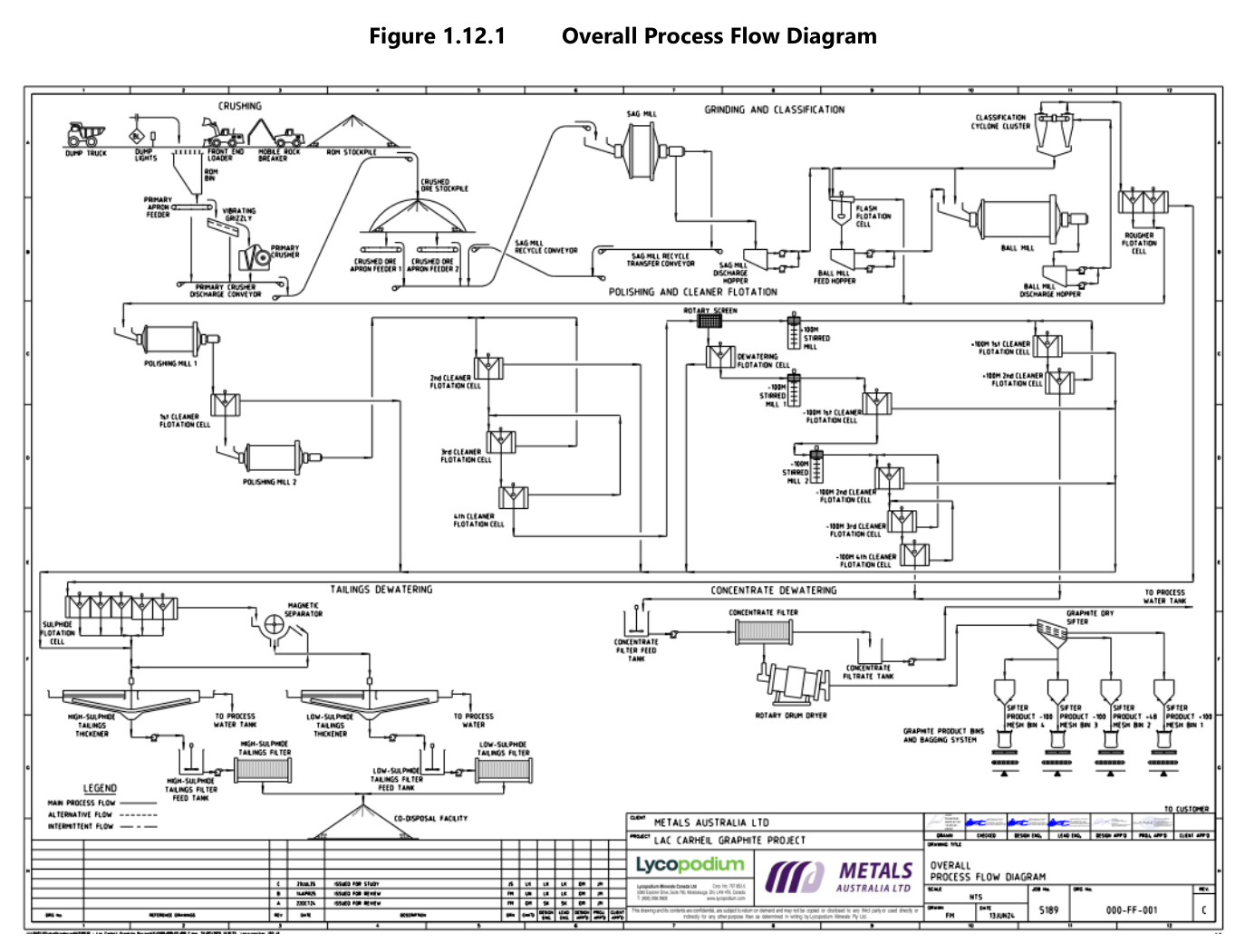
The overall process flow diagram in Figure 17.1.1 presents the unit operations incorporated into the selected flowsheet. The plant layout provides ease of access to all equipment for operating and maintenance requirements while maintaining a layout that facilitates construction progress in multiple areas concurrently.
—
Key Process Stages
Crushing and Crushed Ore Stockpile
Run-of-mine ore is trucked from the pit to a jaw crusher. A vibrating grizzly scalps fine material from the jaw crusher feed before the crusher. The fine material and the crushed material are conveyed together to the crushed ore stockpile via conveyor. The stockpile is covered, and the material is reclaimed from the stockpile for downstream processing.
Milling and Size Classification
The milling circuit includes a SAG mill with a discharge hopper and pumps. After primary milling, the material passes through ball mills and polishing mills. The SAG mill discharge includes a hopper and pumps that return oversize material to the mill feed. Cyclone overflow sizing is set at a P80 of 200 µm, which is a key process design criterion.
The milling circuit includes a rotary screen and associated pumps. Two polishing mills operate in the circuit, with the second polishing mill discharge and the tailings from the third cleaner stage feeding the second cleaner stage. This configuration supports the staged grinding and cleaning approach used to recover graphite at the desired particle sizes.
Flotation and Concentrate Recovery
The flotation circuit uses conventional flotation to recover graphite from the milled ore. Low pressure air for flotation is supplied by air blowers. After flotation, the graphite concentrate is processed through pressure filtration. The filtered concentrate is then dried in a rotary dryer.
Drying and Sizing
The dried concentrate product is conveyed to a free-swinging sifter for sizing into three products: +48M, +100M, and –100M. The sizing step separates the concentrate into distinct products suitable for different applications. A dry graphite sifter is included in the equipment list.
Tailings Handling
High-sulphide tailings are thickened in a high-sulphide tailings thickener and then pumped to a filter feed tank. The thickened high-sulphide tailings are filtered using a high-sulphide tailings filter. Low-sulphide tailings are thickened separately in a low-sulphide tailings thickener. Overflow from both thickeners meets the main process water quality requirements and is stored in a process water tank.
Reagent Handling and Storage
Reagent preparation and storage facilities are located within containment areas designed to accommodate more than the content of the largest tank. Each reagent system is located within its containment area to facilitate return to the respective storage vessel and to avoid mixing incompatible reagents. Storage tanks are equipped with level indicators, instrumentation, and alarms to prevent spills during normal operation. Appropriate ventilation, fire and safety protection, eyewash stations, and Material Safety Data Sheets are provided.
The PAX solution is pumped to the sulphide rougher flotation stage only. Flocculant is dosed to both the low-sulphide and high-sulphide tailings thickeners using variable speed helical rotor style pumps.
Water Supply Systems
Raw water is supplied from Lac Carheil by pontoon mounted raw water pumps and stored in a raw water storage tank within the plant. The raw water is distributed to all areas of the plant as needed. The main process water quality requirements are met by the overflow from both the low-sulphide and high-sulphide tailings thickeners. Raw water provides any additional make-up water requirements.
Potable water is supplied from a well pump to a potable water storage tank and distributed to plant safety showers, site facilities, and other potable water points.
—
Additional Interesting Data and Summary
The high-level equipment list in Table 17.3.1 provides an overview of the major mechanical equipment used in the plant. The list includes equipment for crushing, milling, flotation, filtration, drying, and bagging. A concentrate dryer is specified with a diameter of 2 m and a length of 11 m. The dry graphite sifter dimensions are 2.6 m in length, 2.5 m in width, and 2.55 m in height. Four bagging systems are included, with a maximum capacity of 10 bags per hour per system.
The total connected power for the plant is 10.8 MW with an average power draw of approximately 7.2 MW. Manual sampling will be performed for chemical and physical characterization to prepare product technical data.
The tailings thickener area includes a sump pump, and the tailings filtration area includes a sump pump in the equipment list. The high-sulphide tailings filter handles the thickened high-sulphide tailings pumped from the filter feed tank. A tailings thickener area sump pump is listed among the major equipment.
The process design criteria adopted for the PFS are based on the metallurgical testwork program summarized in Section 13 of the report. The design values are consistent with the locked-cycle flotation testwork and supporting metallurgical investigations. The selected design criteria are considered appropriate for process design and economic evaluation at the PFS level.
The reagent systems required for the process include those for flotation, flocculation, and pH control. Low pressure air for flotation is supplied by air blowers. The PAX solution is dosed to the sulphide rougher flotation stage, while flocculant is added to both tailings thickeners.
The summary of the recovery methods for the Lac Carheil Graphite Project indicates a well-defined flowsheet that integrates crushing, milling, flotation, filtration, drying, and sizing. The design values for recovery and concentrate grade are supported by testwork, and the plant layout is arranged for operational access and construction efficiency. The process water supply is drawn from Lac Carheil, with thickener overflow meeting the main process water quality requirements.
—
Source: Lac Carheil Graphite Project Preliminary Feasibility Study Technical Report, August 2026. Project website: Lac Carheil Graphite Project
