

This report describes the processing facilities at the San Dimas operation as documented in a September 2025 NI-43-101 technical report for the San Dimas Silver/Gold Mine, Durango and Sinaloa States, Mexico.
Report context
The September 2025 NI-43-101 technical report on Mineral Resource and Mineral Reserve Estimates for the San Dimas Silver/Gold Mine, located in Durango and Sinaloa States, Mexico, describes the existing processing plant configuration and recovery methods. The information presented represents the processing plant as configured and operating at the time of the report. This article summarises the recovery methods section of that technical report.
Processing route
Crushing
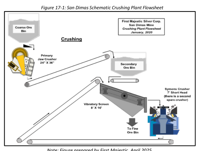
Run-of-mine material from the mines is delivered to a 1,000-tonne capacity steel coarse ore bin equipped with a static screen with 12 x 12-inch apertures. Oversized material retained on the screen is broken down using a hydraulic hammer.
The crushing circuit is designed as a two-stage size reduction process comprising primary and secondary crushing. Coarse ROM ore is discharged from the ROM bin onto a vibrating grizzly feeder, which scalps the -18” +4” fraction for primary crushing. This material is processed by a 20” x 36” primary jaw crusher operating at a closed side setting (CSS) of 3” to 3½”. The crushed product is conveyed to a 450-tonne capacity secondary surge bin.
Material from the secondary bin is fed to an 8’ x 16’ double-deck vibrating screen. The top deck is fitted with slotted apertures measuring 1” x 1½”, while the lower deck uses ½” x ½” openings. The screen undersize (product) typically achieves 90–95% passing 5/16” (8 mm), with an average of 70% passing ¼” (6.4 mm). Oversize material from the vibrating screen is directed to one of two 7’ Symons short head secondary cone crushers, each operated at a CSS of 3/8” to ½”. One unit operates continuously, while the second remains on standby. Secondary crushing reduces the oversize to approximately -5/16”, which is recycled as circulating load back to the vibrating screen feed.
The final undersize product from the vibrating screen is conveyed to two fine ore storage bins (Bins 3 and 4), each with a live capacity of 1,300 metric tonnes. The fine crushed ore product maintains a particle size distribution of 90–95% passing 5/16” (8 mm) and an average moisture content of 3%. The installed capacity of the crushing plant is rated at 220 tonnes per hour (t/h).
Grinding
The grinding circuit comprises three identical ball mills operating in parallel. Each mill has a diameter of 12 feet and a length of 14 feet, driven by a 1,500 HP motor. Classification is performed using Krebs D-20” gMax cyclones, one per grinding line. Each cyclone cluster is supported by a pair of slurry pumps, one operating and one on standby. The grinding media consists exclusively of 3” diameter forged steel balls.
Crushed ore from the fine ore storage bins is conveyed via belt feeders to the ball mills. Reagent addition within the grinding circuit includes cyanide solution (semi-pregnant solution with cyanide concentrations ranging from 2,500 to 3,000 ppm used as process water, with fresh cyanide dosed to maintain a target concentration of 4,000 ppm within the grinding circuit) and lime added to the crushed ore conveyor prior to mill feed, with an average consumption rate of 1.80 kg per tonne of ore processed.
The grinding circuit is designed to achieve a final product with approximately 70% passing 200 mesh (74 µm), corresponding to a P80 of 90 µm. Cyclone overflow gravitates to a trash screen before reporting to two high-capacity primary thickeners operating in parallel. The thickeners have diameters of 55 feet and 48 feet, each with a sidewall height of 12 feet.
Cyanide Leaching Circuit
Leaching at the San Dimas plant involves controlled addition of reagents and a two-stage thickening and leaching process.
Cyanide is added in briquette form at five points: ball mills, and leach tanks 1, 5, 9, and 12, to maintain a cyanide concentration between 3,500 and 4,000 ppm. Cyanide consumption ranges from 1.80 to 2.00 kg/t. Lime is added before the grinding circuit to control leach pH.
The slurry from the grinding circuit is split into two streams, each feeding a primary thickener: Westpro high-capacity units measuring 55’ x 12’ and 48’ x 12’. An anionic flocculant is dosed at 0.11% concentration, equivalent to 25 g/t, to promote solids settling. These thickeners adjust the pulp density ahead of agitated leaching and recover pregnant leach solution (PLS) in the overflow, which is sent to the Merrill-Crowe zinc precipitation circuit.
The thickener overflow (PLS) is transferred to a storage tank, which feeds three 12 m³ Auto-Jet clarifier filters where perlite is used as a filtration aid. The thickener underflow with a pulp density of 1.55 kg/L (58% solids) is diluted with barren solution to a density of 1.40 kg/L (46% solids) before entering the leach tanks.
The primary leaching stage consists of ten agitated tanks operating in series. Tanks #1 and #2 are 50 feet in diameter and 30 feet tall, while tanks #3 to #10 are 30 feet in diameter and 24 feet tall. Low-pressure air is injected into all tanks to maintain approximately 5 ppm of dissolved oxygen.
After primary leaching, the slurry is directed to two intermediate (secondary) thickeners: a 50’ x 12’ Delkor unit and a 48’ x 10’ Westpro thickener. The overflow solution is collected in a semi-pregnant solution tank. Most of this solution recycles to the primary thickener feed or to the PLS tank feeding the Auto-Jet filters, while the remainder is reused in the grinding circuit.
The thickener underflow is pumped to a second leaching stage consisting of six agitated tanks (50’ x 30’ each), equipped with the same low-pressure air injection system and operated under the same parameters as the primary leach tanks.
Counter Current Decantation (CCD) System
Slurry from the final agitated leach tank is directed to the counter-current decantation (CCD) circuit, which consists of two thickeners operating in series. The first stage uses a Delkor thickener with a diameter of 75 feet and a sidewall height of 12 feet, followed by a second stage Outotec thickener measuring 82 feet in diameter and 12 feet in height.
Underflow from CCD #2 is pumped to the final tailings storage tank, which serves as the feed reservoir for three Putzmeister HPS-1500 positive displacement pumps (two duty, one standby). These pumps transfer the tailings slurry to the filtration plant for dewatering.
The overflow from CCD #2 is recycled to the feed of CCD #1, where it mixes with fresh slurry from leach tank #16. CCD #2 also receives barren solution from the Merrill-Crowe filter press circuit, along with filtrate from the tailings filtration plant. Overflow from CCD #1 is collected in the semi-pregnant solution receiver tank.
Merrill-Crowe Zinc Precipitation and Smelting
Pregnant solution is first directed to a storage tank, where turbidity averages approximately 40 nephelometric turbidity units (NTU). The solution is then processed through three auto-jet pressure clarifiers for filtration and clarification. Post-filtration, the clarified solution achieves turbidity levels below 1 NTU.
The clarified pregnant solution is pumped to a de-aeration tower designed for dissolved oxygen removal. This process reduces dissolved oxygen concentrations from approximately 5 ppm to below 1 ppm.
Following de-aeration, the solution is pumped to five filter presses, each 1,500 mm in size and equipped with 62 plates. Prior to filtration, zinc dust is added to the solution to initiate the Merrill-Crowe zinc precipitation reaction. Zinc consumption averages 1.4 kg per kilogram of doré produced. The circuit processes pregnant solution at a throughput of approximately 550 m³/h, with an average metal content of approximately 38 ppm silver (Ag) and approximately 0.7 ppm gold (Au).
The resulting precious metal precipitate is dried in a Holo-Flite screw dryer operating at 225°C, with a nominal capacity of 600 kg/h. Dried precipitate is then smelted in a 1,000 kg capacity induction furnace using silicon carbide crucibles at an operating temperature of 1,100°C. Doré bars produced from this process weigh approximately 32 kg each, with a typical purity of less than 97%. The flux blend used during smelting consists of 7% borax, 7% sodium nitrate, and 0.7% soda ash.
Tailings Filtration and Management
Three Putzmeister positive displacement pumps transfer final tailings slurry from the processing plant to the tailings filtration plant. The slurry is pumped through a 6-inch diameter pipeline, approximately 2 km in length, with a total static lift of 125 metres above pump elevation. The tailings slurry is delivered with a solids content ranging from 56% to 58% by weight.
At the filtration plant, tailings are processed using four horizontal belt filters. The facility includes two units with a filtration area of 64 m² each, and two larger units with a filtration area of 113 m² each. The resulting filter cake is discharged with a residual moisture content of 22% to 24%. The dewatered tailings are then transported and compacted within designated areas of the Tailings Storage Facility (TSF). Filtrate solution recovered from the tailings filtration process is returned to CCD Thickener #2 in the process plant, operating as part of a closed-loop circuit achieving a solution recovery efficiency exceeding 70%.
Key reported parameters
| Parameter | Value | Unit | Basis |
|---|---|---|---|
| Crushing plant installed capacity | 220 | t/h | Design |
| Fine ore bin live capacity (each, 2 bins) | 1,300 | tonnes | Design |
| Grinding product P80 | 90 | µm | Design |
| Grinding product passing 200 mesh | ~70 | % | Design |
| Ball mill dimensions (each, 3 mills) | 12 ft dia. x 14 ft L | feet | Design |
| Ball mill motor power (each) | 1,500 | HP | Design |
| Grinding media size | 3 | inches | Design |
| Lime consumption (grinding) | 1.80 | kg/t | Operating data |
| Cyanide concentration in grinding | 4,000 | ppm | Target |
| Cyanide consumption (leaching) | 1.80–2.00 | kg/t | Operating data |
| Leach cyanide concentration range | 3,500–4,000 | ppm | Target |
| Leach dissolved oxygen | ~5 | ppm | Operating target |
| Primary leach tanks (#1–#2) | 50 ft dia. x 30 ft tall | feet | Design |
| Primary leach tanks (#3–#10) | 30 ft dia. x 24 ft tall | feet | Design |
| Secondary leach tanks (#1–#6) | 50 ft dia. x 30 ft tall | feet | Design |
| CCD #1 thickener (Delkor) | 75 ft dia. x 12 ft | feet | Design |
| CCD #2 thickener (Outotec) | 82 ft dia. x 12 ft | feet | Design |
| Merrill-Crowe throughput | ~550 | m³/h | Operating data |
| Average pregnant solution Ag grade | ~38 | ppm | Operating data |
| Average pregnant solution Au grade | ~0.7 | ppm | Operating data |
| Zinc consumption | 1.4 | kg/kg doré | Operating data |
| De-aeration tower DO reduction | 5 to <1 | ppm | Design |
| Clarified solution turbidity | <1 | NTU | Operating data |
| Precipitate dryer capacity | 600 | kg/h | Design |
| Furnace capacity | 1,000 | kg | Design |
| Doré bar weight | ~32 | kg | Operating data |
| Doré purity | <97 | % | Operating data |
| Smelting flux: borax | 7 | % | Design |
| Smelting flux: sodium nitrate | 7 | % | Design |
| Smelting flux: soda ash | 0.7 | % | Design |
| Tailings pipeline length | ~2 | km | Design |
| Tailings pipeline static lift | 125 | m | Design |
| Tailings slurry solids content | 56–58 | % | Operating data |
| Belt filter area (2 units) | 64 | m² each | Design |
| Belt filter area (2 units) | 113 | m² each | Design |
| Filter cake moisture | 22–24 | % | Operating data |
| Filtrate recovery efficiency | >70 | % | Operating data |
Project website: https://www.firstmajestic.com/projects/producing-mines/san-dimas/
Project website: https://www.accuweather.com/en/us/san-dimas/91773/april-weather/337227
Technical qualifications
The information presented in this article is drawn exclusively from the recovery methods section (Section 17) of the NI-43-101 Technical Report on Mineral Resource and Mineral Reserve Estimates for the San Dimas Silver/Gold Mine, dated September 2025. The report was prepared for First Majestic. The processing plant described is the existing operating facility at the time of the report. All parameters labelled as design values represent installed or designed capacities and specifications. Parameters labelled as operating data represent typical or average historical performance values reported in the technical report. No testwork data from metallurgical testing programs were described in the recovery methods section of the source report. The flowsheet figures referenced in the source report (Figure 17-1 and Figure 17-2) are not reproduced here.
—
Source: NI-43-101 Technical Report on Mineral Resource and Mineral Reserve Estimates, San Dimas Silver/Gold Mine, Durango and Sinaloa States, Mexico, September 2025, Section 17: Recovery Methods.
