

Located in Québec, Canada, the Troilus Gold-Copper Project is a development-stage property owned by Troilus Mining Corp. The project targets gold and copper ore from four deposits and is designed to produce a copper concentrate with gold credits plus gold doré. The technical report carries an effective date of December 31, 2025, and a signature date of September 8, 2026. Construction timing is not stated in the source material.
Critical Data
| Parameter | Value | Unit | Notes |
|---|---|---|---|
| Nominal throughput | 50,000 | t/d | At 88% plant availability |
| Design head grade gold | 0.74 | g Au/t | Nominal head grade: 0.488 g Au/t |
| Design head grade silver | 1.49 | g Ag/t | Nominal head grade: 1.00 g Ag/t |
| Design head grade copper | 0.09 | % Cu | Nominal head grade: 0.058% Cu |
| LOM overall gold recovery | 86.7 | % Au | At 0.488 g/t head grade |
| LOM overall copper recovery | 89.6 | % Cu | At 0.058% head grade |
| LOM gravity gold recovery | 31.9 | % Au | Not stated |
| Primary grinding product P80 | 75 | µm | Design value |
| Regrind product P80 | 20 | µm | Design value |
| Bond ball mill work index (BWi) | 16.18 | kWh/t | 82nd percentile, test result |
| Bond crusher work index (CWi) | 22.5 | kWh/t | Estimated from Axb |
| Plant availability target (Years 1-3) | 88 | % | Design value |
| Plant availability target (Year 4+) | 91.5 | % | Target value |
| Process plant power demand | 76 | MW | Calculated average operating demand |
| Annual energy consumption | 619 | GWh | LOM estimate |
Overview
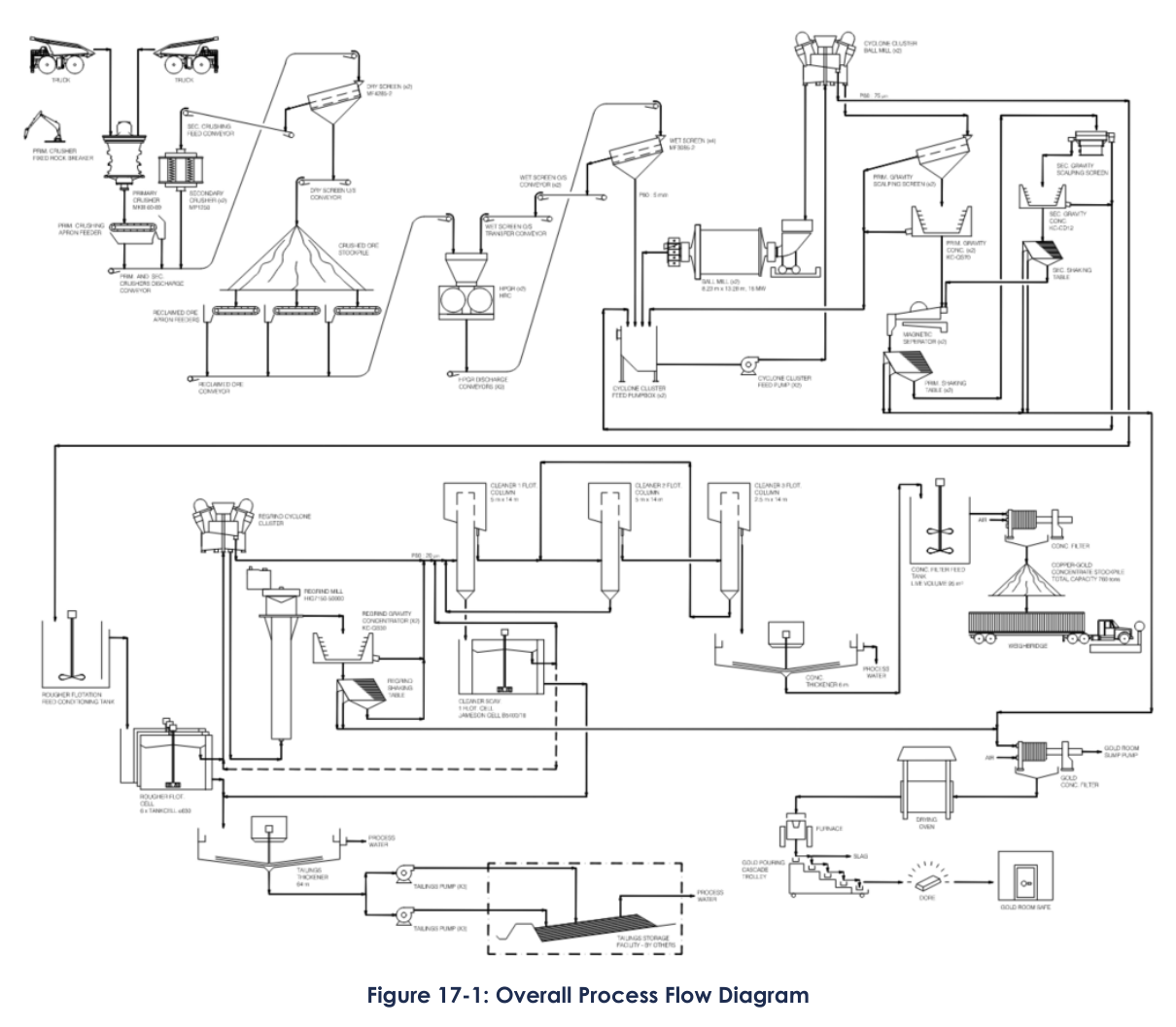
The process plant flowsheet uses two-stage crushing, grinding, gravity concentration, and flotation. Ore will feed an open circuit gyratory crusher followed by two parallel closed-circuit secondary cone crushers. That arrangement produces a 48 mm top size for the high-pressure grinding rolls. The HPGRs operate in closed circuit with wet vibrating screens. Material then moves to two parallel closed ball milling circuits with gravity concentration. Rougher and scavenger flotation produces a primary copper concentrate. That concentrate is reground and sent to three stages of column flotation cleaning plus a cleaner-scavenger stage. Final concentrate is thickened and filtered. Gravity concentrates from three points in the circuit are smelted to produce doré.
Ramp-up planning targets 60% of nominal design within six months to achieve commercial production. Another ten months will be needed to reach full capacity. From Year 3, maintenance will shift toward predictive and preventive work. The redundant HPGR and ball mill line will allow an increase in annual plant production of around 725,000 tonnes based on 3.5% availability.
Key Process Stages
Primary crushing starts with run-of-mine ore dumped directly or reclaimed by front-end loader into the ROM bin. The primary crusher fixed rock breaker handles oversize material. An apron feeder controls feed rate and overall throughput. Material discharges onto a conveyor with a cross-belt magnet for tramp metal removal. A dust collection system with hoods, ducting, and baghouse manages dust in this area.
Secondary crushing and screening use a dry screen feed bin that splits feed onto two feeders with variable speed drives. The dry screen undersize at P80 of 37 mm goes to a crushed ore stockpile dome that provides surge capacity between crushing and the rest of the plant. The oversize returns to the secondary crushers. Each area has a dedicated dust collection system.
The stockpile reclaim and HPGR section uses three apron feeders to control feed rate from the dome. The reclaimed ore conveyor feeds the HPGR feed bin, which splits material onto two variable-speed feeders. Metal detectors protect the HPGR rollers. Each HPGR discharge conveyor feeds a wet screen feed bin with two screens. Wet screen undersize at P80 of 2.7 mm goes to the cyclone cluster feed pumpboxes. The oversize returns to the HPGR feed bin.
Grinding occurs in two identical parallel lines. Slurry from the cyclone cluster feed pumpbox goes to the ball mill cyclone cluster. Cyclone overflow at F80 of 75 µm goes to the rougher flotation feed conditioning tank. Cyclone underflow splits with 64% going to the ball mill and 36% to the primary gravity circuit. Each ball mill has a retractable feed chute and trunnion magnet. Lime is added at the ball mill feed chute.
Primary gravity concentration uses a portion of the cyclone underflow. The material passes through scalping screens to protect concentrators. In the concentrators, high centrifugal forces separate heavier particles including gold into riffles. Lighter particles flow over the bed as tailings. Concentrate is discharged after a fixed cycle time. A magnetic separator removes steel particles before the material goes to a primary shaking table.
Secondary gravity concentration operates as a single line. Feed goes through a scalping screen and into a secondary concentrator. The same centrifugal separation principle applies. Concentrate is discharged to a storage tank before feeding a secondary shaking table. Tails from secondary concentration return to the primary concentrate storage tanks.
Rougher flotation receives cyclone overflow from both milling trains in a single conditioning tank with approximately six minutes residence time. Frother and collector are metered in. Lime adjusts pH, with most added at the mill feed. Slurry goes to one line of six 630 m³ rougher mechanical flotation cells. Concentrate goes to the regrind circuit. Tails go to the flotation tails pumpbox.
The regrind circuit reduces rougher concentrate to P80 of 20 µm before cleaner flotation. A regrind cyclone cluster operates in open circuit with a vertical stirred regrind mill. The regrind cyclone overflow at P80 of 20 µm goes to the first cleaner conditioning tank. Mill discharge goes to the regrind gravity distribution box.
Regrind gravity uses two concentrators. The same centrifugal separation principle captures heavy particles. Concentrate is collected in a storage tank and fed to a regrind shaking table. Concentrate from that table goes to the gold concentrate filter feed tank. Tails return to the regrind gravity tails transfer pumpbox.
The cleaner flotation circuit has three stages of column flotation and a cleaner-scavenger circuit with three mechanical cells. Each column receives conditioned feed at about two thirds of its height. A portion of the column tails recirculates to generate cavitation for fine bubble distribution. Wash water at the column top improves concentrate grade. Concentrate flows by gravity between stages. The third column discharges final gold-copper concentrate to the thickener feed box. Slurry samplers at multiple points feed the on-stream analyzer.
Concentrate thickening and filtration use a 6 m diameter high-rate thickener and a filter press. Flocculant is added through an inline static mixer. Thickener underflow at approximately 65% solids goes to an agitated filter feed tank with 12 hours surge capacity. The filter press removes water to reach a target moisture of approximately 10% using pressing and air blowing steps. Filter cake is loaded by front-end loader for off-site truck shipment.
The gold room collects gravity concentrates from all three shaking table circuits. Material is filtered, dried, mixed with fluxes, and loaded into an induction furnace. The induction furnace produces doré ingots at a design frequency of one smelt per week. Fluxes react with base metal oxides to form slag. The slag is returned to the ball mill feed chute by hand.
Tailings from rougher and cleaner-scavenger flotation go to a 64 m diameter high-rate thickener. Flocculant is added through an inline static mixer. Thickener underflow at a target of 60% solids is pumped to the tailings storage facility. Overflow flows by gravity to the process water tank for reuse.
Additional Interesting Data and Summary
The process plant power demand is 76 MW average operating with an additional 1.60 MW for tailings and surface water management. Annual LOM energy consumption is estimated at 619 GWh. The process water tank holds 3,413 m³ for 0.5 hours surge capacity based on average consumption of 5,946 m³/h. Raw water from Lake A goes to a 1,233 m³ tank with 864 m³ dedicated as fire water reserve. Average raw water requirement is 281 m³/h with peak intermittent consumption of 514 m³/h.
Reagent consumption data from the process design criteria shows lime consumption of 1.54 kg/t, frother consumption of 25 g/t for rougher and 4 g/t for cleaner, PAX consumption of 48 g/t for rougher and 8 g/t for cleaner, SPRI 206 consumption of 28 g/t for rougher and 6 g/t for cleaner, and flocculant consumption of 30 g/t for the tailings thickener and 15 g/t for the concentrate thickener.
The project uses four metallurgical accounting cross-linear samplers at strategic locations across the plant. They measure metal grades in cyclone overflow, tailings thickener underflow, and the concentrate filter feed tank. These samplers support plant reconciliation and metal production reporting.
High-pressure air at 750 kPa comes from two rotary compressors in lead-lag configuration. Low-pressure air at approximately 230 kPa for the rougher and cleaner-scavenger circuit is supplied by two centrifugal blowers. Compressed air at 550 kPa for the flotation columns is stepped down from the 750 kPa supply.
The report recommends conducting a detailed bottleneck analysis across various areas of the process plant to identify potential constraints and define required optimization measures. This recommendation aims to support a potential throughput of 18.98 Mt/y starting from Year 4, subject to validation of assumptions about feed hardness, plant availability, and achieved operational performance.
Key Processes
- Two-stage crushing with open circuit gyratory crusher and parallel closed-circuit secondary cone crushers
- HPGR circuit operating in closed circuit with wet vibrating screens
- Two parallel closed ball milling circuits with cyclones
- Primary gravity concentration with scalping screens and centrifugal concentrators
- Secondary gravity concentration with centrifugal concentrator and shaking table
- Rougher and scavenger mechanical flotation cells (six cells at 630 m³ each)
- Regrind circuit with vertical stirred mill and cyclone cluster
- Regrind gravity concentration with centrifugal concentrators and shaking table
- Three-stage column flotation cleaning in series
- Cleaner-scavenger circuit with three mechanical cells
- Concentrate thickening with 6 m diameter high-rate thickener
- Concentrate filtration with filter press (target 10% moisture)
- Gold room with filter press, drying oven, and induction furnace for doré production
- Tailings thickening with 64 m diameter high-rate thickener
- On-stream analyzer for real-time flotation circuit monitoring
- Metallurgical accounting samplers at four plant locations
Source: NI 43-101 Technical Report: Troilus Gold – Copper Project, Québec, Canada, December 31, 2025. Project website: Troilus Gold-Copper Project
Consolidated report summaries
The following former standalone pages about this operation were consolidated here on October 25, 2026. They are retained for source traceability; dates and figures reflect each report’s own effective date and may be superseded by the current information above.
Mineral Processing Circuit of Troilus Mine
The technical report does not provide detailed information on processing and recovery methods, as Section 17 (Recovery Methods) explicitly states: “This section is not relevant to this report.”
However, the report does contain relevant geological and mineral resource details that may indirectly inform potential processing approaches:
Key Observations on Potential Processing & Recovery:
1. Mineralization Characteristics:
– The Troilus deposit is a gold-copper system with minor silver, zinc, lead, and traces of bismuth, tellurium, and molybdenum.
– Two mineralization styles are noted: disseminated and vein-hosted, with gold spatially correlated with sulphides (though sulphide content does not directly correlate with grade).
– Host rocks include diorite breccia, diorite, and felsic dikes.
2. Historical Context:
– The Z87 and J4/J5 Zones were previously mined via open pit (1996–2010), suggesting conventional crushing, grinding, and flotation/cyanidation may have been used.
– No specific historical recovery rates or metallurgical data are provided in this report.
3. Metallurgical Work Planned:
– The report mentions that metallurgical testwork was underway in summer 2020 to support a pre-feasibility study, but results are not included.
– Recommendations include re-analyzing 2018 drill samples for silver and bulk density, indicating these elements may influence future processing plans.
4. Resource Estimates (Indicative of Feed Material):
– Open-pit resources:
– Indicated: 164.2 Mt @ 0.68 g/t Au, 0.08% Cu, 1.20 g/t Ag.
– Inferred: 101.2 Mt @ 0.60 g/t Au, 0.07% Cu, 1.12 g/t Ag.
– Underground resources (higher grade):
– Indicated: 13.1 Mt @ 1.61 g/t Au, 0.13% Cu.
– Inferred: 15.5 Mt @ 1.62 g/t Au, 0.11% Cu.
5. Potential Processing Challenges & Considerations:
– Gold association with sulphides suggests flotation or oxidative pre-treatment (e.g., pressure oxidation, bioleaching) may be required if gold is refractory.
– Copper content could necessitate a Cu-Au separation circuit (e.g., selective flotation).
– Low silver grades may not justify dedicated recovery but could be a byproduct.
6. Innovations & Future Work:
– The report emphasizes the need for further drilling and metallurgical studies to define optimal recovery methods.
– No specific equipment or flow sheets are discussed, but the presence of copper and variable gold grades implies a need for tailored processing.
Conclusion:
While the report confirms the project’s mineral resource potential, it defers detailed processing and recovery discussions to future studies (e.g., PEA/pre-feasibility). Historical mining suggests conventional methods were previously applied, but updated metallurgical data will be critical for designing the modern circuit.
—
Let me know if you’d like further elaboration on any aspect.
