

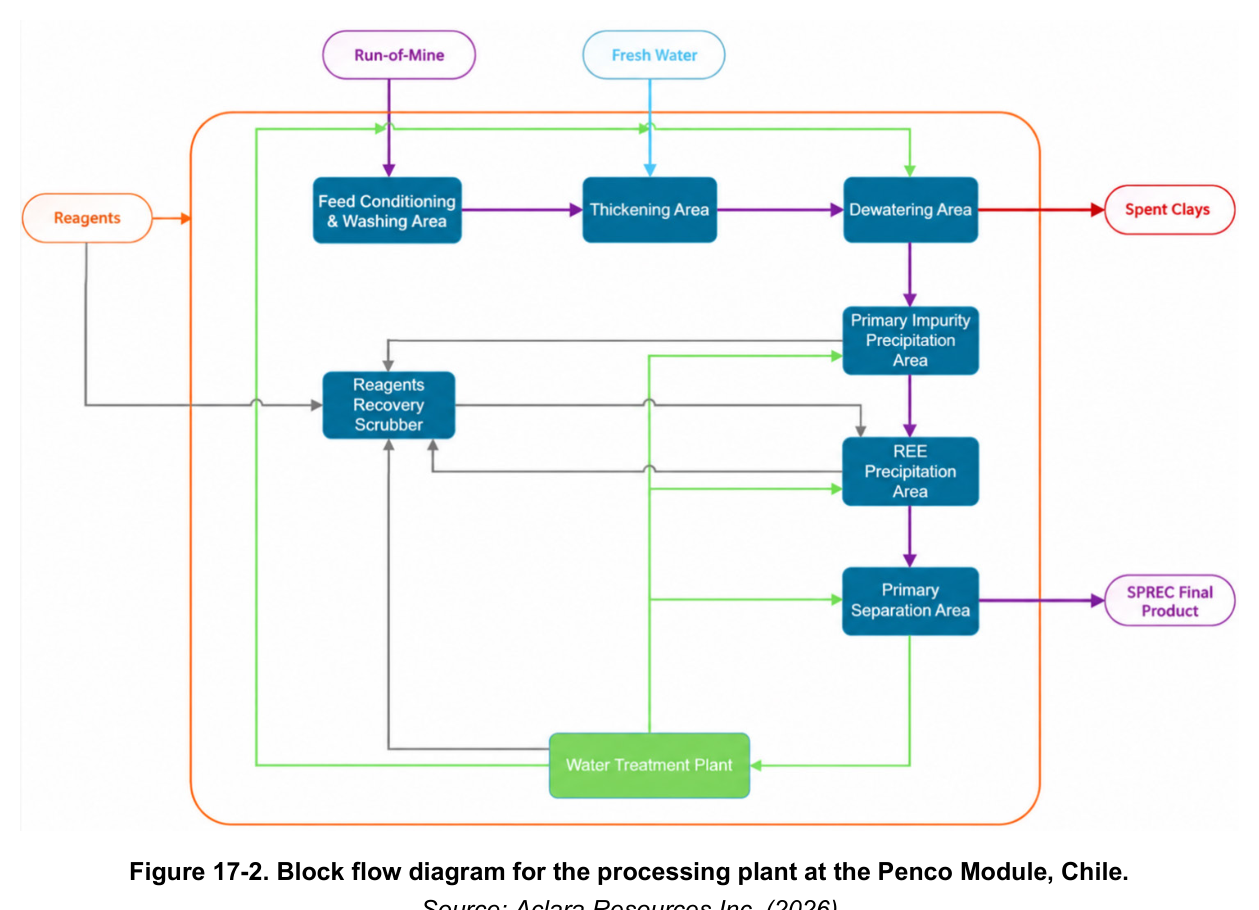
The recovery flowsheet for this Biobío ionic clay project produces a super pure rare earth carbonate through washing, impurity precipitation, and selective separation, with water and reagent recycling built in.
Aclara Resources Inc. holds the Penco Module, an ionic clay rare earth project in the Biobío Region of Chile. The NI 43-101 Technical Report and Preliminary Economic Assessment presents the project as a development-stage operation with a processing design built around Aclara's patented Circular Mineral Harvesting process. That flowsheet recovers rare earth elements from run-of-mine clay and produces a super pure rare earth carbonate (SPREC) as the final product. The plant is designed to treat approximately 320 t/h of solids and to achieve an equivalent average rare earth oxide production rate of approximately 777 t/year, excluding ramp-up and ramp-down periods. The facility layout keeps vehicle transit separated from areas exposed to high dust levels or to the chemical processes used for REE extraction.
Critical Data
| Parameter | Value | Unit | Notes |
|---|---|---|---|
| Design solids throughput | 320 | t/h | Design flow rate |
| Average REO production | 777 | t/year | Equivalent average, excluding ramp-up and ramp-down |
| Processed wet mineral | 278 | t/h | Mass balance input |
| Dry mineral | 236 | t/h | Mass balance input |
| Fresh mineral moisture | 15.3 | % | Mass balance input |
| REE grade | 1,906 | ppm | Mass balance input |
| REO grade | 2,257 | ppm | Mass balance input |
| Wet SPREC production | 2,530 | t/year | Dry filtered product |
| SPREC carbonate grade | 98.9 | % | Mass balance based estimation |
| Purity, REO equivalent | 98.1 | % | Mass balance based estimation |
| Desorption without cerium | 29.1 | % | Metallurgical performance |
| Desorption with cerium | 20.2 | % | Metallurgical performance |
| Plant yield | 87.2 | % | Metallurgical performance |
| Overall performance | 17.7 | % | Total recovery |
| Mean desorption | 20.2 | % | Mean across REEs |
| Mean plant recovery | 87.2 | % | Mean across REEs |
| Mean total recovery | 17.7 | % | Mean across REEs |
| Fresh water consumption | 20.8 | m3/h | Process requirement |
| Thickener underflow solids | 50 | % by mass | Approximate, for filter press feed |
| Wet screen cut size | 1 | mm | Removes particles larger than 1 mm |
| Wash water pH, trommel | 10 | pH | Clean alkaline water |
| Strong filtrate first wash | 4 | pH | Low-pH washing step |
| Weak filtrate second wash | 10 | pH | Washing step |
| Fresh water recycling | 97 | % | WTP design figure |
| Ammonium sulphate recycling | 99 | % | WTP design figure |
Overview
The processing plant recovers REEs from raw ionic clay feed. Run-of-mine material is conditioned into a slurry through the addition of a low-pH solution, which enables an ion exchange process that transfers REEs into solution. The feed conditioning stage includes two feeders, a washing drum, screening, thickening, and filtration, and it concludes with the recovery of a pregnant solution containing the REEs. That stream goes to a primary precipitation stage, while the washed clays are transported to the deposition zone.
The primary precipitate is redissolved, and the resulting REE-rich solution passes through successive chemical stages that remove impurities before the final REE carbonate product is made. Impurity removal takes place in a primary precipitation stage built around two reactors where pH is adjusted and reagents are added. A polishing filtration stage removes solid impurities from the product stream. A similar process then precipitates REEs from the resulting filtrate solution. Recirculated clean solutions serve the backwashing and solids washing steps, and precipitated impurities return to the feed conditioning stage.
The final production stage separates REEs, reducing light REEs such as lanthanum and cerium along with other impurities through selective separation, chemical precipitation, and filtration. Final SPREC is filtered in tube press filters and bagged for client distribution. Filtrate streams from all solid and liquid separation processes go to a water treatment plant (WTP) that produces water suitable for reintroduction into the feed circuit. The treated water is reused in a closed loop, which reduces overall water consumption, limits make-up water demand, and prevents discharge of process water to the environment. The WTP is designed to generate water of sufficient quality for washing spent clays so they are suitable for deposition. Its incorporation enables recycling of approximately 97% of fresh water and 99% of the ammonium sulphate.
Key Process Stages
Mined ionic clay arrives at the plant by truck from the various Penco Module pits. Material is normally dumped into one of two feed hoppers or onto a temporary stockpile. Each hopper has a static grizzly that rejects vegetation, rocks, and other material unsuitable for processing, and that reject material goes to final disposal at the deposition zone. Clay passing the grizzly flows by gravity into the hopper and then by belt feeder to a wobbler classifier that removes oversized material which could damage downstream processes. The oversized material is later transported to the deposition zone.
Undersized material enters the washing drum. A metal detector on the feed conveyor identifies unwanted objects that could damage the drum or downstream pumps. Leaching solution is added to the washing drum feed to generate the slurry and start the desorption process. Washing drum discharge flows into a trommel that removes coarse particles, and those particles are washed with clean alkaline water at pH 10. Fine material passing the trommel flows by gravity to wet screening, where two vibrating screens in series remove particles larger than 1 mm. The same wash water brings the slurry to the desired concentration and supports screening efficiency. Fine particles passing the wet screens flow by gravity to a slurry transfer box and are pumped to thickening. Coarse particles from the trommel and wet screening go to a coarse material conveyor belt for stacking and trucking to the deposition zone.
In the thickening area, slurry is pumped to a thickener where flocculant is added to enhance sedimentation of solids. The underflow stream reaches a slurry solids concentration of approximately 50% by mass, as required for feeding the filter presses. The REE-rich thickener overflow flows by gravity into a thickener overflow tank. Part of this stream is pumped to the reactors in the primary impurity precipitation area, and the rest returns to the washing drum to enhance size separation performance. Thickener underflow is pumped to the filter press feed tank in the dewatering area.
Dewatering uses two membrane-type plate and frame pressure filters. Their objective is to maximize recovery of REE-rich solution from the slurry and to obtain low-moisture spent clays that can be disposed of sustainably. A strong filtrate, high in REE content, combines the filtered solution from the filtering feed, the membrane squeeze, and the first washing step at low pH. Solution from these three filtering stages flows by gravity into the filter filtrate tank and is pumped to the primary precipitation area. A weak filtrate, low in REE content, comes from the second washing step at pH 10. It is discharged into a washing water tank and pumped to the multimedia filtering feed tank at the WTP. The cloth wash and core blow steps generate a stream containing solids that flows by gravity to a dedicated tank and is pumped back to the thickening area to recover the solids. Clean wash water at the end of each filtration cycle displaces residual REEs remaining in the filter cake. After each cycle, the low-moisture washed clay is discharged via feeders onto a conveyor belt system that transports it to a stockpile for trucking to final disposal in the deposition zone.
The process produces two types of washed clays: coarse material from the oversize of trommel and screening equipment, and fine material in the form of filter cakes from the press filters. These materials are collected independently on separate conveyor belts, each with weightometers that allow metallurgical accounting. Each residue product is discharged onto separate stockpiles and used specifically in the deposition zone according to its physical characteristics, which facilitates operation of that zone.
In the primary impurity precipitation area, the strong filtrate from dewatering and a portion of the thickener overflow are pumped to the coprecipitation feed tank, a holding tank for the area. The solution then goes to the primary impurities coprecipitation system, two reactors in series where anhydrous ammonia is added to promote impurity precipitation. The mixture is pumped from the second reactor to one of three impurities polishing filters to produce a clear solution. Filtered solid impurities are discharged on a batch basis and pumped back to the thickening area. The filtrate solution is stored in a filtrate coprecipitation tank and pumped to the primary REE precipitation area.
In the REE precipitation area, clarified solution from the coprecipitation tank is pumped to the REE reactors, where ammonium bicarbonate is added to precipitate the REE. Anhydrous ammonia is also available to control pH as required. Three polishing filters are fed from the coprecipitation feed tank to recover the precipitated REE as a dilute slurry. The high-REE-content slurry discharged from the polishing filters is pumped to the primary separation area. The filtrate solution, which contains high total dissolved solids, is stored in a filter solution tank before being pumped to a multimedia filtering tank in the WTP.
The primary separation area processes the REE-rich slurry from the REE precipitation area. It reduces the concentration of lighter REEs such as lanthanum and cerium and improves the quality of the REE product. Purification is achieved through selective separation, chemical precipitation, and filtration to obtain the final SPREC wet product. The SPREC is filtered and transferred to the packing system, where flexible intermediate bulk container (FIBC) bags are filled. The FIBCs are removed from the bagging system by forklift and stored in the product storage and dispatch warehouse, ready for shipment by truck.
The WTP is included in the process design to minimize fresh water consumption and avoid the need for a plant liquid discharge stream. The process system recovers water and removes impurities that could affect final product quality. Its design features neutralization, nanofiltration, reverse osmosis, and ion exchange.
Scrubbers treat off-gases from the impurity and REE precipitation areas, the primary separation area, reagent preparation tanks, neutralization reactors, the WTP clarifier, the WTP filter press feed tank, and the water recovery system (WRS) recovered solution tank. The main objective of the off-gas scrubbing system is to recover ammonium bicarbonate and ammonium sulphate and recycle them back to the processing plant, ensuring these gases are not released into the environment.
The process water distribution system collects and stores dilute solution rejected from WTP nanofiltration and other process streams in two treated water tanks. Dilute solution in one tank is adjusted to pH 4 using sulphuric acid, and solution in the other is adjusted to pH 10 using ammonium hydroxide. The treated water is pumped to the pressure filters, wet screens, and washing drums as required. Fresh water is supplied to the project by trucks, received into one of two freshwater storage tanks, and distributed to the service water system (including firefighting), the pH 4 solution distribution tank, mine services, and plant areas plus utilities where fresh water is required. All drainage and rainwater flow by gravity to a collection sump, and excess water is sent to leaching solution tank #1 in the reverse osmosis area of the WTP.
Compressed air is generated to meet plant, process, and instrumentation air requirements. The main air consumers are the impurities, primary separation, and WTP areas, and the main equipment requiring air supply includes the filter presses, polishing filters, and product tube press filters. Instrument air is generated from compressed air after passing through air dryers and filters, then stored in dedicated instrument air receivers. Potable water is supplied by truck and received in the potable water tank, from which it is pumped to the process plant safety showers and other areas where it is required for human use and consumption, such as the dining room, offices, and restrooms. Areas with corrosive materials have emergency showers with eyewashes.
Additional Interesting Data and Summary
The total recovery of 17.7% was determined from the metallurgical program REE precipitation reactions using Condition B results combined with the primary separation process. Rare earth element extraction data from metallurgical data and geochemical information were used as inputs to the mining plan, which in turn provided inputs for process facility design, including the annual flow of mined material to the plant. An average flow rate was used to develop the mass balance for subsequent equipment selection and design, including the REE grades and recoveries throughout the useful life of the project. Design criteria for the solid and liquid separation and washing systems were selected based on vendor testing programs on samples from the pilot plant. The parameters used in mass balance calculations were obtained from laboratory tests conducted in accordance with the mining plan.
Recovery varies widely by element. Plant recovery reaches 94.3% for praseodymium, 94.8% for neodymium, 95.8% for europium, 97.8% for gadolinium, 95.7% for terbium, 96.2% for dysprosium and holmium, 95.4% for erbium, 94.8% for thulium, 94.0% for ytterbium, 93.4% for lutetium, and 97.7% for yttrium. Desorption ranges from 2.1% for cerium to 61.0% for yttrium, with a mean of 20.2%. Total recovery by element ranges from 0.5% for cerium to 59.6% for yttrium. The plant recovery mean is 87.2%.
The mass balance sets processed wet mineral at 278 t/h and dry mineral at 236 t/h, with fresh mineral moisture of 15.3%. Feed grades are 1,906 ppm REE and 2,257 ppm REO. Wet SPREC production is 2,530 t/year, with a SPREC carbonate grade of 98.9% and a purity of 98.1% REO equivalent, both mass balance based estimations. Fresh water consumption is 20.8 m3/h.
Key Processes
- Run-of-mine clay reception, grizzly rejection, wobbler classification, and metal detection
- Low-pH leaching and washing in drums with trommel and wet screening at a 1 mm cut
- Thickening with flocculant to approximately 50% solids underflow
- Dewatering by two membrane-type plate and frame pressure filters with strong and weak filtrate separation
- Primary impurity precipitation in two reactors using anhydrous ammonia, with three polishing filters
- REE precipitation using ammonium bicarbonate, with ammonia for pH control and three polishing filters
- Primary separation through selective separation, chemical precipitation, and filtration
- SPREC filtration in tube press filters and FIBC bagging
- Water treatment by neutralization, nanofiltration, reverse osmosis, and ion exchange
- Off-gas scrubbing to recover ammonium bicarbonate and ammonium sulphate
- Treated water distribution at pH 4 and pH 10, with trucked fresh and potable water supply
Source: NI 43-101 Technical Report & Preliminary Economic Assessment on the Penco Module, Biobío, Chile, 2026-09-18. Project website: Penco Module
