

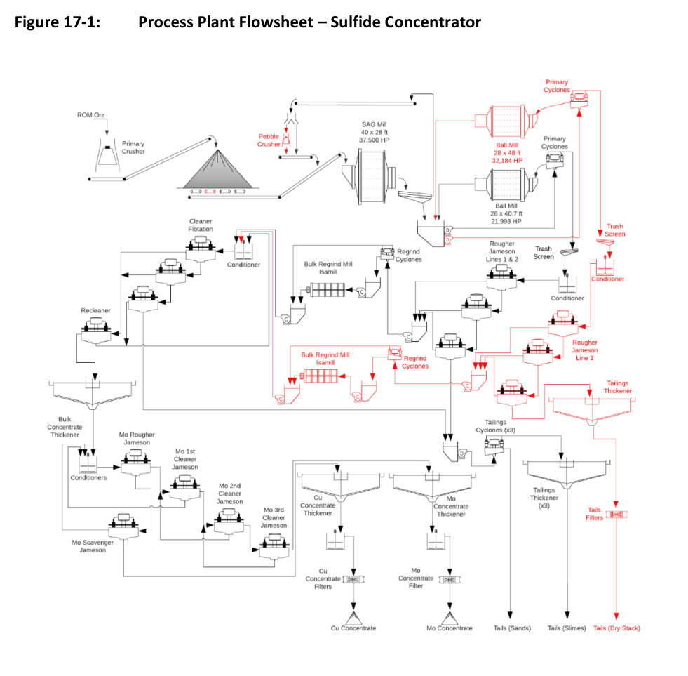
A 60,000 st/d copper and molybdenum concentrator with a planned expansion to 90,000 st/d, detailed in the Copper World definitive feasibility study.
Copper World is a copper and molybdenum project in Pima County, Arizona, USA, about 28 miles (45 km) southeast of Tucson in the historic Helvetia Mining District. Hudbay Minerals Inc. holds 70% of the project through Copper World LLC, with Mitsubishi Corporation holding the remaining 30%. The 2026 Definitive Feasibility Study sets out a Base Case mine plan that requires only state and local permits, and it supports an initial investment in the concentrator together with pre-feasibility studies for a mill expansion and an in-pit crushing and conveying system. The flowsheet produces copper concentrate and molybdenum concentrate.
Critical Data
| Parameter | Value | Unit | Notes |
|---|---|---|---|
| Plant design capacity, initial | 60,000 | st/d | 21,900,000 st/a |
| Plant design capacity, expansion | 90,000 | st/d | 32,850,000 st/a |
| Nominal grinding throughput, initial | 2,720 | st/h | |
| Grinding throughput, expansion | 4,076 | st/h | |
| Plant availability, grinding and flotation | 92 | % | |
| Crusher runtime, design | 75 | % | Both crushing arrangements |
| Crushing feed size, F80 | 15 | inch | F100 of 39 inches |
| Crushing product size, P80 | 6.0 | inch | |
| Grinding product size, P80 | 150 | µm | Maintained after expansion |
| SAG mill dimensions | 40 x 28 | ft | Grate discharge with pebble ports |
| Ball mill 1 dimensions | 26 x 40 | ft | Overflow, closed circuit |
| Ball mill 2 dimensions | 28 x 48 | ft | Expansion |
| ROM specific gravity, nominal for design | 2.84 | Not applicable | Range 2.7 to 2.9 |
| Plant ore feed grade, LOM average copper total | 0.50 | % w/w | Design maximum 0.89% |
| Plant ore feed grade, LOM average molybdenum | 0.01 | % w/w | Design maximum 0.14% |
| Bulk cleaner concentrate grade, copper | 25 | % w/w | Target |
| Molybdenum concentrate grade | 50 | % Mo | By weight |
| Copper filter cake moisture, design | 10 | % | |
| Molybdenum filter cake moisture, design | 15 | % | |
| Molybdenum final cake moisture | 5 | % | After drying |
| Dry-stack tailings filter cake moisture | 14 | % | Expansion |
| Bulk concentrate thickener underflow density, design | 60 | % solids w/w |
Overview
The Recovery Methods section rests on a series of engineering studies completed by DRA for Hudbay. A definitive feasibility study covered the initial 60,000 st/d concentrator. A pre-feasibility study addressed the expansion to 90,000 st/d from Year 5 onward, and a further pre-feasibility study examined the addition of an in-pit crushing and conveying circuit.
Processing works by flotation to produce a copper concentrate, with an oxidative leach option that would also produce copper cathode. The plant design has been updated from the 2023 PFS to take in process and flowsheet optimizations arising from additional metallurgical testwork at various laboratories, and to defer a decision on concentrate leaching.
The concentrator is designed to run two 12-hour shifts per day, 365 days per year, at an overall plant availability of 92%.
Key Process Stages
Crushing and stockpiling
Run-of-mine ore arrives by 320 st rear-dump haul trucks at a primary crusher operating in open circuit. Trucks dump from either side of a two-sided pocket with a live capacity of 361 st. For Years 1 to 4, a plant-side gyratory crusher (Sandvik CG850i) of 1,300 HP handles a design feed rate of 3,333 stph. From Year 5 onward an in-pit crusher of 670 HP, with a nominal feed rate of 5,000 stph and a design rate of 6,500 stph, supplements the plant-side unit. Crushed ore moves by overland and aerial conveyors to the coarse ore stockpile feed conveyor.
Both arrangements reduce ore from a design F80 of 15 inches to a product P80 of 6.0 inches. The plant-side crusher discharges into a surge pocket, and a variable speed apron feeder carries the ore to the stockpile, which has a live capacity of 60,000 st, or 24 hours of residence time. Two operating feeders and one standby reclaim apron feeder withdraw ore onto the SAG mill feed conveyor. The expansion adds a fourth feeder, giving three operating and one standby. Rock breakers at both crushing facilities handle oversize, and dust suppression and dust collectors serve the dumping, crushing and conveyor transfer points.
Grinding and classification
The initial grinding circuit pairs a 40 ft by 28 ft SAG mill with a 40 ft by 26 ft ball mill in closed circuit with a cyclone cluster, a SAB arrangement. Ore is reduced from an F80 of 6.0 inches to a P80 of 150 µm. The SAG mill runs a grate discharge with pebble ports into a trommel and a vibrating screen deck with 0.6 inch apertures. Screen undersize gravitates to the cyclone feed pumpbox, and oversize returns to the SAG mill feed conveyor.
The expansion adds a pebble crusher, converting the circuit to SABC, and a second ball mill of 48 ft by 28 ft in closed circuit with its own cyclone cluster, while holding the 150 µm target. The pebble crushing circuit has two vibrating feeders, each feeding a 1,100 HP cone crusher. Pebbles can bypass the crushers through a diverter gate ahead of the surge bin. The ball mill circuit is designed for a nominal circulating load of 250% and a design maximum of 350%.
Bulk flotation and regrinding
Cyclone overflow gravitates to a diverter box that splits the stream to two rougher flotation lines. The streams pass trash screens to bulk rougher conditioning tanks, where collector, frother and NaHS are added, and lime may be added when ore carries high pyrite. The conditioned slurry is pumped to Jameson Cells. Initially the bulk rougher circuit has two trains of three Jameson Cells (Model B8500/12, 27.9 ft diameter). The expansion adds a conditioning tank and a third train, bringing circuit capacity to 90,000 st/d. Rougher concentrate from all lines combines inline and reports to a concentrate hopper through a metallurgical sampler and analyzer.
Rougher concentrate is pumped to a regrind mill (M20000 IsaMill, 6,700 HP) in open circuit, with cyclones ahead of the mill removing minus 32 µm particles and the underflow discharging to the IsaMill feed hopper. Water is added to hold the feed below 20% solids w/v. The regrind circuit produces a P80 of 32 µm.
Cleaning
Bulk regrind product joins the regrind cyclone overflow and is pumped to a cleaner conditioning tank for collector, pH modifiers and frother. High pyrite ore may draw lime and cyanide as depressants. The bulk cleaner circuit has four Jameson flotation cells (Model B6500/24, 21.3 ft diameter): three cleaner cells in series and a recleaner. Cleaner 1 can run as first cleaner or as a cleaner scalper. The recleaner produces final concentrate targeting 25% w/w copper, and its tails return to Cleaner 2. Piping allows cleaner tails to be directed back to the second rougher cell when slower floating minerals need improved recovery. Bulk rougher tailings join bulk cleaner final tailings and flow to the final tailings tank through a metallurgical sampler.
Molybdenum separation and dewatering
Bulk concentrate is thickened in a single 79 ft high-rate thickener using flocculant. Underflow at about 60% solids w/w is pumped to molybdenum rougher conditioning tanks in series, where sodium hydrosulfide and carbon dioxide suppress copper minerals, with fuel oil, dispersant and frother added. The molybdenum circuit uses Jameson Cells throughout: one rougher and one scavenger (Model E2514/3) followed by three cleaner stages of one cell each (Model Z1200/1), producing a concentrate of 50% Mo by weight. Molybdenum rougher tails report to the copper thickener.
Copper concentrate, the molybdenum flotation tailings, is thickened in a 79 ft high-rate thickener. Two pressure filters are installed initially and a third arrives with the expansion. Filter cake design moisture is 10%. Molybdenum concentrate is thickened in a 20 ft high-rate thickener, filtered to a target cake design moisture of 15%, then dried in a paddle dryer to a final cake moisture of 5%. Dried concentrate is bagged in 2 st bulk bags for truck transport.
Tailings
Combined tailings pass through hydrocyclones for sand and slime separation, generating a fines deficient sands stream for building the tailings storage facility embankments. A distribution box redirects one third of the sands to tailings filtration during the expansion. Slime overflow goes to a thickener feed distributor serving three 164 ft high-density thickeners initially, each with its own cyclone cluster. Two trains of centrifugal pumps carry underflow to the storage facility, with three pumps in series initially and five after expansion.
The expansion adds a fourth 164 ft thickener and four filter presses (three duty, one standby). One third of the slimes and one third of the sands are combined in a tailings filter feed plant tank, thickened, and filtered to a cake targeting 14% moisture. The cake is conveyed to radial stackers for dry stacking.
Additional Interesting Data and Summary
Water for the plant comes from wells on the western side of the Santa Rita Mountains and is pumped to a freshwater tank for reagent mixing, slurry pump gland seals and mill lubrication system cooling. Process water is drawn from tailings and concentrate thickener overflows, storage facility reclaim and seepage ponds, and the freshwater tank as needed. A process water pond and tank form the distribution loop, and tailings thickener overflow discharges directly to the process water tank.
Reagents arrive in bulk. Collectors come as 30% w/w liquid in 20-ton road tankers and are diluted to 10% w/w. Sodium hydrosulfide arrives at 45% w/w in 24-ton tankers and is diluted to 15% w/w, with tank vapor vented through a caustic scrubber. Flocculant is delivered as dry powder and mixed to a 0.25% w/w solution. Quicklime arrives as coarse powder and is slaked in a ball mill to produce milk of lime at 20% w/w solids.
Three separate plant air compressors serve the plant. All flotation cells are self-aspirated. An onsite assay laboratory, provided by a third party under contract, serves the mine and process plant.
The design parameters above describe the concentrator as engineered. The expansion capabilities from 60,000 to 90,000 st/d are built into the initial design layout, with the additional equipment listed for the expansion phase.
Key Processes
- Primary crushing in an open-circuit gyratory crusher, with an in-pit crusher added from Year 5
- Coarse ore stockpiling with a 60,000 st live capacity
- SAB grinding to a P80 of 150 µm, moving to SABC with a pebble crusher at expansion
- Bulk copper-molybdenum rougher flotation in Jameson Cells
- Open-circuit regrinding in an IsaMill to a P80 of 32 µm
- Bulk cleaning and recleaning to a final concentrate target of 25% w/w copper
- Molybdenum flotation with three cleaner stages to a 50% Mo concentrate
- Copper and molybdenum concentrate thickening, filtration and drying
- Tailings sand and slime separation with thickening, and filtration with dry stacking in the expansion
Source: NI 43-101 Technical Report, Definitive Feasibility Study and Updated Mineral Reserve and Mineral Resource Estimates, Copper World Project, Pima County, Arizona, USA, 2026-10-20. Project website: Copper World Project
