

The Horne 5 Gold Project is an advanced development project located in Rouyn-Noranda, Québec, Canada, owned by Falco Resources Ltd. The project targets gold, with associated copper, zinc, and silver credits, and is planned as an underground mining operation. The project is currently at the feasibility study stage, with the 2026 Feasibility Study Update serving as the most recent technical report. The source document identifies an effective date of June 11, 2026, with a signature date of July 24, 2026. The technical report does not state specific construction timing or a development decision, and those details are not included here.
Critical Data
| Parameter | Value | Unit | Notes |
|---|---|---|---|
| Nominal plant throughput | 15,000 | tpd | Based on 92% availability |
| Average hourly throughput | 679 | dry tonnes | At nominal plant throughput |
| Early years throughput capability | 16,000 | tpd | First five years following commissioning and ramp-up |
| Primary grind target | 50-60 | µm | P80 to flotation |
| Average feed grade, Cu | 0.158 | % | From February 2017 mine plan |
| Average feed grade, Zn | 0.739 | % | From February 2017 mine plan |
| Average feed grade, S | 16.31 | % | From February 2017 mine plan |
| Average feed grade, Au | 1.34 | g/t | From February 2017 mine plan |
| Average feed grade, Ag | 13.4 | g/t | From February 2017 mine plan |
| Design sulphur content, pyrite concentrate case | 23 | % S | 80th percentile of sulphur distribution |
| Design sulphur content, grinding case | 10 | % S | 20th percentile of sulphur distribution |
| SAG mill installed power | 18.7 | kWh/t | Pinion power |
| Ball mill installed power | 18.7 | kWh/t | Pinion power |
| SAG mill required power, design ore | 12.5 | kWh/t | Nominal tonnage |
| Ball mill required power, design ore | 16.9 | kWh/t | Pinion, nominal tonnage |
| SAG mill required power, average ore | 11.3 | kWh/t | Nominal tonnage |
| Ball mill required power, average ore | 16.2 | kWh/t | Pinion, nominal tonnage |
| Pyrite concentrate regrind target | 10-12 | µm | P80 to leach circuit |
| Pyrite concentrate pre-oxidation retention | 8 | h | Design |
| Pyrite concentrate leach retention | 16 | h | Design |
| Flotation tails leach retention | 12 | h | Design |
| Carbon stripping capacity | 24 | t/batch | Design |
| Process plant personnel | 88 | workers | Excludes nine paste backfill workers |
| Total yearly electricity consumption | 580,740 | MWh | At nominal throughput of 15,000 tpd |
| Natural gas, stripping and kiln | 2.76 | Mm³/y | Carbon stripping solution and regeneration kiln |
| Natural gas, building heating | 3.54 | Mm³/y | Building air exchange heating |
| Process water requirement | 33,000 | m³/day | Approximate |
| Cyanide-bearing process water | 5,700 | m³/day | Approximate |
| Fresh water consumption | 1,600 | m³/day | Approximate |
| Live stockpile volume | 5,000 | m³ | Approximately 16 hours at nominal throughput |
| Paste backfill production capacity | 16,384 | tpd | Prepared wet paste |
| Paste backfill availability | 57.3 | % | Design |
| Paste solids content | 76.3 | % w/w | 50:50 blend of PFT and PCT |
| Binder content | 3.5 | % | 80:20 slag-to-cement blend |
| Carbon processing rate | 21.5 | tpd | Loaded carbon from both CIP circuits |
| Elution circuit capacity | 24 | tpd | Carbon |
| Carbon reactivation kiln | 1,000 | kg/h | 24 t/day, 750°C |
| Design dissolved metal loading, pyrite concentrate CIP | 1.18 | mg/L Au | Design |
| Design dissolved metal loading, pyrite concentrate CIP | 10.45 | mg/L Ag | Design |
| Design dissolved metal loading, pyrite tails CIP | 0.25 | mg/L Au | Design |
| Design dissolved metal loading, pyrite tails CIP | 2.49 | mg/L Ag | Design |
| Adsorption efficiency, pyrite concentrate CIP | 99.6 | % Au | At average grade |
| Adsorption efficiency, pyrite concentrate CIP | 98.8 | % Ag | At average grade |
| Adsorption efficiency, pyrite tails CIP | 98.9 | % Au | At average grade |
| Adsorption efficiency, pyrite tails CIP | 94.3 | % Ag | At average grade |
Overview
The recovery methods selected for the Horne 5 Project were developed from laboratory-scale metallurgical testwork performed on numerous composites prepared from drill core sections. The retained flowsheet shows the results of comprehensive testwork programs completed between 2015 and 2017 and forms the basis for the process plant design and the development of capital and operating cost estimates. Additional confirmatory testwork is recommended prior to detailed engineering to validate key metallurgical assumptions and support final equipment selection.
The presence of cyanide-consuming base metals in the ore led to the selection of a flowsheet incorporating three flotation circuits upstream of the precious metals recovery circuits, minimizing cyanide consumption while maximizing overall gold recovery. The first two flotation circuits selectively recover copper and zinc into saleable concentrates. The tailings from the zinc flotation circuit are subsequently treated in a third flotation circuit to recover a pyrite concentrate. Testwork indicated that this product requires fine regrinding to optimize gold and silver extraction by cyanide leaching. The testwork further demonstrated that residual precious metals contained in the pyrite flotation tailings can also be recovered by cyanide leaching without regrinding.
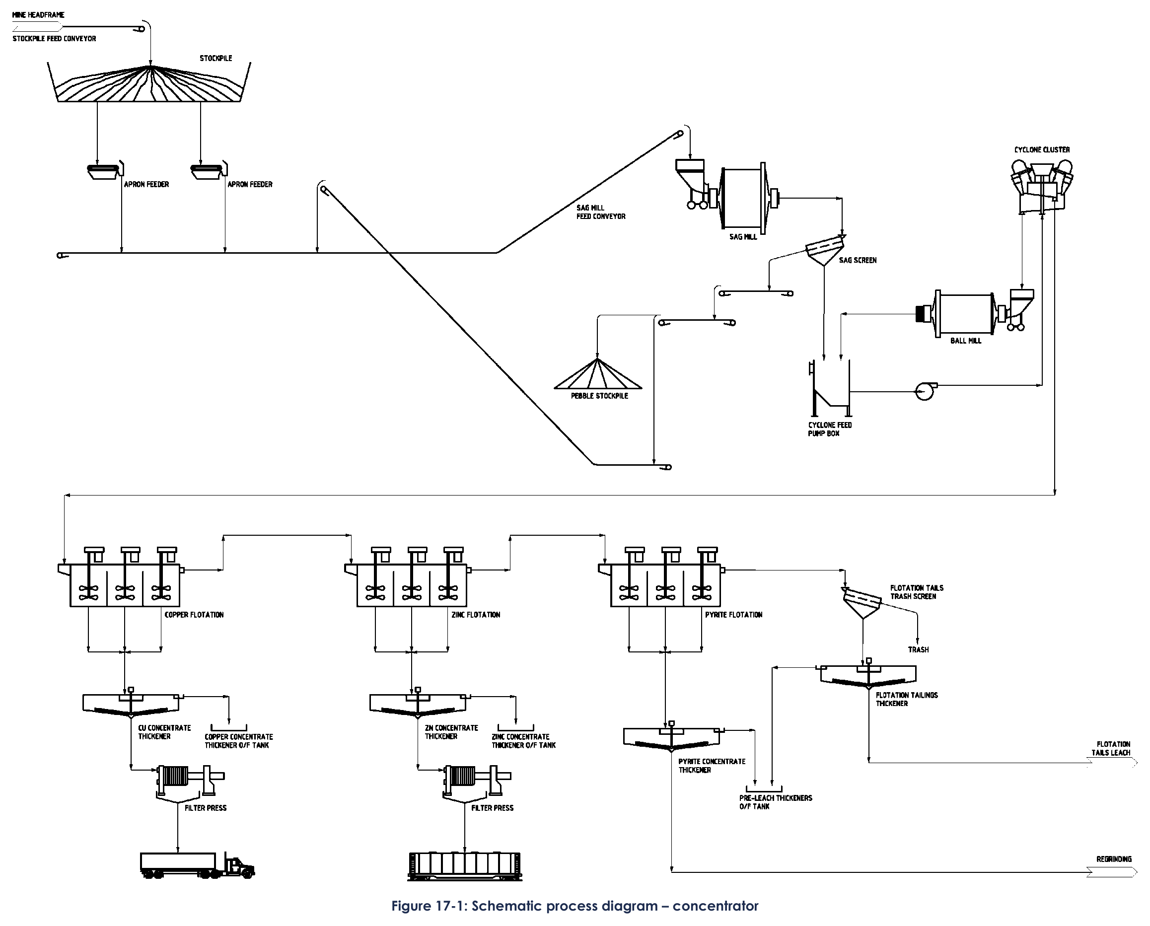
The process plant consists of ore reclaim, grinding, differential flotation of copper, zinc and pyrite, base metal concentrate dewatering, fine regrinding of the pyrite concentrate, gold leaching of the pyrite concentrate and pyrite flotation tailings followed by dedicated carbon-in-pulp and cyanide destruction circuits, gold elution and refinery, paste backfill preparation using a blend of pyrite concentrate tailings and pyrite flotation tailings, reagent preparation systems, and process water, fresh water, low-pressure air and compressed air distribution systems. These process areas are designed to produce saleable copper and zinc concentrates and gold doré for delivery to customers.
Copper concentrate is planned to be transported by truck, while zinc concentrate will be loaded onto railcars for shipment. The addition of a rail spur to the mine site also provides the opportunity to receive paste backfill additives and other bulk reagents by rail.
Key Process Stages
The process plant design criteria are based on a nominal throughput of 15,000 tpd and an overall plant availability of 92%, corresponding to an average hourly throughput of 679 dry tonnes. Peak tonnages of 115% were generally applied to process areas where flow rates are not significantly influenced by feed grade, including ore reclaim, grinding and rougher flotation. For downstream circuits, equipment sizing is governed by the concentration of specific elements in the feed. Copper and zinc grades determine the sizing of the respective flotation cleaning and concentrate dewatering circuits, while sulphur content governs the capacities required for pyrite concentrate regrinding, pre-leach and pre-detoxification thickening, leaching, CIP and cyanide destruction, as well as those associated with the pyrite flotation tails stream.
The process plant was designed with sufficient flexibility to accommodate a nominal throughput of 16,000 tpd during the first five years of operation following commissioning and ramp-up. The final throughput profile over the mine life should be reviewed during detailed engineering based on the final mine production schedule.
The initial process plant design basis was developed using the February 2017 mine plan provided by Falco, which comprised 92.8 Mt of mineralized material with an average sulphur content of 16.3% over an 18-year mine life. This mine plan remains the basis of the 2026 Feasibility Study. Design grades for copper, zinc, gold and silver were established by considering the peak annual average grades from the mine plan and applying a factor of 125%. Sulphur content is the most critical process design parameter because it influences both comminution and the downstream precious metals recovery circuits.
The sulphur design criteria were established through an analysis of the cumulative tonnage versus sulphur grade distribution of individual stopes included in the mine plan. Direct sulphur assays were not available in the historical drill hole database, so InnovExplo estimated sulphur contents by converting measured core specific gravity values into sulphur grades using a regression relationship developed by Noranda. This approach assumes that the high-density fraction of the ore is predominantly associated with pyrite, while the lower-density fraction is associated with rhyolite.
For design purposes, the 80th percentile of the sulphur distribution was used to establish the maximum pyrite concentrate production scenario. The selected design sulphur content for this case was 23% S and governs the sizing of the pyrite concentrate handling, regrinding and associated precious metals recovery circuits. Comminution testwork demonstrated an inverse relationship between sulphur content and ore hardness, whereby lower sulphur grades correspond to harder ore. Consequently, a second design sulphur content corresponding to the 20th percentile of the distribution was established. This harder ore scenario governs the sizing of the grinding circuit and represents the maximum pyrite flotation tails production case. The selected design sulphur content for this scenario was 10% S.
Crushing is performed in the underground mine, and the crushed material is hoisted to the surface and discharged via a stockpile feed conveyor onto a stockpile located in a domed structure. Plant feed is reclaimed from the covered coarse ore stockpile using two variable-speed apron feeders located beneath the stockpile. Each apron feeder is sized to sustain the design plant throughput independently, though both feeders operate simultaneously under normal operation. The live stockpile volume is approximately 5,000 m³, equivalent to approximately 16 hours of operation at the nominal plant throughput.
The retained grinding circuit consists of a SAG mill operating in closed circuit with a vibrating screen, followed by a ball mill operating in closed circuit with hydrocyclones. A SAG mill measuring 10.97 m × 5.41 m EGL was selected to provide the required 8.5 MW of pinion power for the design ore. The mill drive train incorporates a twin-pinion arrangement driven by two 6.7 MW low-speed synchronous motors. A ball mill measuring 7.62 m × 11.43 m EGL provides the required 11.5 MW of pinion power for the design ore. The ball mill operates in closed circuit with a cluster of 400 mm hydrocyclones, producing a flotation feed with a target P80 of 55 µm at a slurry density of approximately 35% solids by weight.
The flotation section comprises three principal circuits dedicated to the recovery of copper, zinc and pyrite concentrates. Gold and silver are recovered in association with each of these concentrate streams. Precious metals reporting to the copper and zinc concentrates are recovered through the respective smelting processes. Precious metals reporting to the pyrite concentrate and flotation tailings are subsequently recovered through downstream leaching circuits located after the pyrite flotation stage. The copper and zinc flotation circuits each consist of rougher and cleaner flotation stages designed to produce saleable concentrates meeting the required grade and recovery targets. The pyrite flotation circuit comprises a rougher flotation stage only, producing a pyrite concentrate for subsequent precious metals recovery.
The copper flotation circuit uses five 130 m³ rougher cells with a design retention time of 20 minutes, followed by a cleaning circuit with three stages of cleaning closed by a cleaner-scavenger. The zinc flotation circuit uses five 70 m³ rougher cells with a nominal retention time of almost 11 minutes, followed by a similarly configured cleaning circuit. The pyrite rougher flotation uses six 130 m³ cells providing a nominal retention time of 24 minutes.
Both the pyrite concentrate and pyrite flotation tailings are leached with cyanide for recovery of gold and silver values. The pyrite concentrate leaching circuit comprises four cyanidation tanks installed in series, providing an overall retention time of 16 hours. For the flotation tails, four tanks of Ø13 m are used to reach the required retention time of 12 hours. All the leaching tanks are provided with individual metered oxygen sparging and staged metered addition points for cyanide and lime for pH control.
The leached slurries of pyrite concentrate and tails flow through their respective line of CIP tanks, each with an inventory of 6 mesh x 12 mesh activated carbon used to adsorb the dissolved gold and silver values. The CIP train for the pyrite concentrate includes eight tanks of 300 m³ each, while the one for the pyrite flotation tails has six tanks of 130 m³.
The gold recovery circuits are based on the processing of 21.5 tpd of loaded carbon, with 15 tpd coming from the pyrite concentrate CIP circuit and 6.5 t each day from the tailings. An elution circuit for handling 24 tpd of carbon is specified. Carbon elution follows the high-pressure Zadra process, with a barren strip solution of 2% NaOH and 0.2% NaCN circulating at an elevated temperature and pressure through the two elution columns in a serial configuration. The nominal strip solution temperature is 135°C, and a pressure control valve maintains the column at a nominal pressure of 650 kPa.
Three parallel trains of two electrowinning cells each recover gold and silver from the pregnant strip solution. The electrowinning cells are fitted with stainless steel anodes and stainless steel wool cathodes. Fluxes are mixed with the dried and cooled electrowinning sludge, and the mixture is charged to the electric induction smelting furnace. Gold and silver doré is poured from the furnace into moulds arranged in a cascade on a trolley. At the average head grades and projected recoveries per circuit, the sludge is expected to carry 8% gold and 77% silver, with the remainder as impurities.
Cyanide destruction is completed using Caro's acid, generated by reacting hydrogen peroxide and sulphuric acid together. Two parallel cyanide destruction circuits treat the respective thickened CIP circuit tailings, with one tank providing a retention time of 30 minutes per circuit. The treated streams are then pumped either to the paste backfill plant preparation or to the project's tailings storage areas.
The paste backfill circuit is located within the processing plant, adjacent to the flotation area. Paste is produced at 76.3% solids using a 50:50 blend of pyrite flotation tails and pyrite concentrate tails with a binder content of 3.5% consisting of an 80:20 slag-to-cement blend. This paste recipe is expected to achieve unconfined compressive strengths of 200 kPa and 1,000 kPa after 12 and 28 days, respectively.
Additional Interesting Data and Summary
The reagent systems follow a standard configuration where each liquid reagent has a reception tank capable of holding approximately 1.5 truckloads. The last tank in each reagent system is the distribution tank, with metering pumps or pumps feeding a pressurized distribution loop. The flocculant preparation system consists of a dry flocculant hopper followed by a polymer screw conveyor and blower-eductor that transfers measured amounts of powder through a wetting head. The distribution tank holds 12 hours of design consumption at the 0.5% w/w flocculant strength.
Quicklime is delivered via trucks to a 575 t silo providing on-site inventory for 3 days of design consumption. The packaged slaking facility generates an 18% w/w quicklime solution at a design rate of 8 tph. Cyanide is delivered in the form of briquettes with a built-in alkaline buffer, provided in 17.3 t reusable isotainers. Each batch dissolves one complete isotainer to a 23% w/w cyanide solution. Oxygen is delivered to site in tanker trucks and stored in three 50 t tanks.
The process plant has three distinct process water systems: process water receiving water from the pre-leach and concentrate thickener overflows, filtrate from the paste backfill plant, and make-up from mine clarified water; cyanide-bearing process water receiving cyanide-laced water recovered from the overflow streams of the pre-detoxification thickeners; and fresh water for uses such as carbon elution, reagent preparation, equipment cooling and pump gland sealing. The process water systems have been divided into cyanide-free and cyanide-bearing circuits since introduction of cyanide to the flotation circuits would act as a gold depressant.
A total of 88 workers are required in the process plant, including 34 salaried staff and 54 hourly workers divided into management and technical services, operations and maintenance departments. Nine workers for the paste backfill area are excluded from these totals. The metallurgical testwork programs provide a comprehensive basis for the selection of the process flowsheet, the projected recoveries of gold, silver, copper and zinc, and the sizing of the principal process equipment. The results demonstrated that plant performance is influenced by feed sulphur content and base metal grades, highlighting the importance of maintaining a consistent plant feed.
The following opportunities have been identified to further reduce technical risk and optimize the process plant prior to detailed engineering: complete a continuous mini-pilot plant campaign using a representative life-of-mine composite; complete locked-cycle flotation variability testing on selected composites; develop an ore blending strategy for high-grade and low-grade ore zones; review the sizing of the primary grinding mills using the final mine plan sulphur distribution; review historical flotation testwork with equipment suppliers; and confirm the suitability of the selected fine regrinding technology. These activities are not expected to materially alter the selected process flowsheet but would further reduce technical and execution risks and increase confidence in the process design prior to detailed engineering.
Key Processes
- Crushing is performed underground; ore is hoisted and stored in a covered domed stockpile
- Grinding uses a SAG mill in closed circuit with a vibrating screen, followed by a ball mill in closed circuit with hydrocyclones
- Differential flotation recovers copper, zinc, and pyrite concentrates using mechanically agitated tank cells
- Copper and zinc concentrates are dewatered by thickening and pressure filtration before direct shipping
- Pyrite concentrate undergoes high-intensity fine regrinding in three vertical mills with ceramic media
- Pyrite concentrate and flotation tailings are leached with cyanide in separate circuits
- Pre-oxidation of pyrite concentrate reduces sulphide activity and cyanide and oxygen consumption
- Carbon-in-pulp circuits use activated carbon to adsorb dissolved gold and silver
- Gold recovery uses high-pressure Zadra elution, electrowinning, and induction furnace smelting to produce doré
- Cyanide destruction uses Caro's acid generated from hydrogen peroxide and sulphuric acid
- Paste backfill is prepared from a blend of pyrite concentrate and pyrite flotation tailings with slag-cement binder
- Process water systems are separated into cyanide-free and cyanide-bearing circuits
Source: 2026 Feasibility Study Update, Horne 5 Gold Project, July 24, 2026. Project website: Horne 5 Gold Project
Technical report and processing history
The following archived source profiles have been consolidated here to preserve the project’s processing history and study context.
Horne 5 Gold Project — 2021 Technical Report
Horne 5 Gold Project — 2021 Technical Report
| Company | Falco Resources Ltd. |
| Date | 2021 |
| Region | Abitibi, Quebec, Canada |
| Commodities | Gold, Silver, Copper, Zinc |
| Mine Type | Underground |
| Throughput | 15,000 tpd |
| Mine Life | 18 years |
| Status | Development |
Executive Summary
The Horne 5 Gold Project Feasibility Study Update by Falco Resources Ltd. presents a detailed processing plant design for the recovery of gold, silver, copper, and zinc from sulphide ore. The flowsheet, based on SGS Lakefield laboratory testwork, utilizes a differential flotation circuit to separate copper, zinc, and pyrite concentrates, followed by cyanide leaching for precious metal recovery from the pyrite stream. The plant is designed for a nominal throughput of 15,000 tonnes per day with an 18-year mine life based on the February 2017 mine plan.
The grinding circuit consists of a SAG mill and ball mill, with a specific regrinding circuit for the pyrite concentrate using HIG mills to liberate gold and silver. Concentrate dewatering is achieved via thickeners and pressure filters, with copper concentrate shipped by truck and zinc concentrate by rail. The facility also includes a paste backfill plant utilizing tailings and backfill materials to support underground mining operations.
Gold recovery involves Carbon-in-Pulp (CIP) circuits, elution using the Zadra process, electrowinning, and smelting to doré bars. The plant incorporates extensive automation, reagent systems, and cyanide destruction circuits to ensure environmental compliance and operational efficiency. Design criteria account for ore hardness variability linked to sulphur content, ensuring robust equipment sizing for the expected mine life.
Reports
Entities
Concepts
Website: https://www.falcores.com/en/horne-5-project/
Report Date: 2021
Region: Abitibi, Quebec, Canada
Project Status: Development
Commodity: Gold, Silver, Copper, Zinc
Throughput: 15,000 tpd
Mine Life: 18 years
Mine Type: Underground
Ore type:
Horne 5 Project — 2016 Technical Report
Horne 5 Project — 2016 Technical Report
| Company | Falco Resources |
| Date | 2016 |
| Region | Abitibi, Quebec |
| Commodities | Gold, Silver, Copper, Zinc |
| Throughput | 15,000 tpd |
| Mine Life | 12 years |
| Status | Development |
Executive Summary
This NI 43-101 Technical Report outlines the recovery methods for the Horne 5 Project, based on laboratory-scale testwork performed at SGS Lakefield laboratory. The proposed flowsheet involves a differential flotation circuit to recover copper and zinc concentrates prior to cyanidation, with a subsequent pyrite flotation stage to recover pyrite for gold and silver leaching. The processing plant is designed for a nominal throughput of 15,000 tpd with a 12-year mine life.
The plant design includes underground crushing, SAG and ball milling circuits, and a complex flotation section for copper, zinc, and pyrite. Gold and silver recovery is achieved through cyanide leaching of the pyrite concentrate and flotation tails, followed by Carbon-in-Pulp (CIP) circuits. The final products include copper and zinc concentrates for delivery by truck and rail, and gold doré bars.
Processing Overview
- Crushing: Underground crushing and conveyor to surface stockpile.
- Grinding: SAG mill (Ø10.36m) and Ball mill (Ø7.31m) in closed circuit.
- Flotation: Differential flotation for Cu, Zn, and Pyrite using tank cells.
- Leaching: Cyanide leaching of pyrite concentrate and tails.
- Recovery: Carbon-in-Pulp (CIP) circuits for gold and silver adsorption.
Website: https://www.falcores.com/en/horne-5-project/
Report Date: 2016
Region: Abitibi, Quebec
Project Status: Development
Commodity: Gold, Silver, Copper, Zinc
Throughput: 15,000 tpd
Mine Life: 12 years
Mine Type:
Ore type:
