

This report presents the proposed processing design for the Superior Zinc and Copper Project, based on a bankable feasibility study, with design criteria developed from historical and current test work.
Report context
This technical report, dated October 2021, covers the feasibility study for the Superior Zinc and Copper Project. Section 17 (Recovery Methods) was prepared by DRA based on the Superior Lake Bankable Feasibility Study dated September 27, 2019, and presented to Superior Lake Resources. The section was prepared for the NI 43-101 technical report on the project. The processing facilities are designed for underground ore from the Pick Lake deposit, to be treated through sequential flotation to produce separate copper and zinc concentrates.
Processing route
Design philosophy
The processing facilities are based on sequential flotation of underground ore from the Pick Lake deposit to produce separate copper and zinc concentrates. The plant has been designed in accordance with accepted industry practice, with the flowsheet comprising unit operations well proven in industry and based on results of historical test work and the test work program detailed in Section 13 of the source report.
The plant will operate on a 365 d/a, 24 h/d operating cycle with design crushing plant and grinding circuit utilisation of 85% for a nominal ore throughput of 44 dry t/h. The design basis assumes a moderate level of instrumentation and automation to minimise operator requirement without introducing undue complexity and expense. The design adheres to well-proven and conservative design practice appropriate to the copper and zinc flotation industries.
Crushing and stockpiling
The crushing plant will have a capacity of 327,600 tpa ROM ore and will crush underground ore from the Pick Lake orebody. Ore will be blended on the ROM pad to provide uniform feed to the crushing, milling, and flotation circuits. The ROM pad will contain up to 6,000 tonnes of stockpiled ore to provide a buffer between the mine and plant, allowing blending of feed stocks for up to 14 days.
The crushing plant will be provided and operated by an independent contractor using a mobile/modular multi-stage crushing and screening circuit, with a nominal throughput of 53 t/h representing 70% utilisation for 327,600 tpa throughput. Material will be fed and recovered from the crushing circuit by front-end loader or similar. Crushed product size is designed at P₈₀ of 134 mm. A magnet positioned at the conveyor head chute will remove tramp metal. The surge bin will have live capacity of approximately 230 m³ (10-hour live capacity). In normal operation, the grinding circuit will be fed from the surge bin with excess feed generating stockpile. A dust collector at the surge bin will discharge collected dust onto the mill feed conveyor.
The ores are mildly abrasive with an Ai value of 0.32. The ROM bin, surge bin, and all transfer chutes will incorporate wear liners.
Grinding and classification
The grinding circuit will consist of a single stage SAG mill operating in closed circuit with hydrocyclones. The SAG mill will be a 5.49 m diameter x 2.90 m EGL unit equipped with a 1,400-kW drive, operating at up to a maximum 32% volumetric charge loading, with a speed range of 65 to 80% critical speed. The mill will have steel lifters and liners and include grate discharge. Nominal circuit P₈₀ grind size is 75 µm.
Cyclones will be used for classification, with underflow returning via gravity to the SAG mill. The cyclone cluster will comprise three 250 mm diameter cyclones (2 duty, 1 standby). Cyclone overflow will report to a trash screen to remove oversize particles and plastic, with screen underflow feeding an agitated flotation feed surge tank. Raw water will be added to achieve target density of 38% solids w/w. Duty/standby flotation feed pumps transfer slurry to copper rougher conditioning tank.
A ball charging system will provide 100 mm steel balls to the SAG mill. Provision for addition of milk of lime slurry to the SAG mill feed will be made to assist in depression of pyrite and zinc in copper flotation. Pebbles from the SAG mill will be conveyed to a scats bunker for recycling. Process water will be added to the slurry in the cyclone feed hopper.
Copper flotation
Copper flotation will include roughing and scavenging stages fed at slurry density of 34% solids w/w, followed by cleaning, cleaner scavenging, and recleaning stages. Slurry from the flotation feed surge tank will be pumped at a controlled rate to the first of two agitated copper rougher conditioning tanks. The feed stream will be sampled via an automated cross stream slurry cutter for metallurgical accounting. Low pressure air will be added into the base of the tank to assist in passivation of reactive gangue sulphide minerals. Reagent additions to the first conditioning tank will include depressant (sodium metabisulphite, SMBS) and lime.
Slurry will overflow the first conditioning tank into the second, providing a total conditioning time of 30 minutes. Additional slurry streams into the second tank include copper first cleaner scavenger tails, returning flotation feed slurry sample, and slurry spillage from the area sump pump. Reagent additions to the second conditioning tank include depressant (SMBS), copper collector (Aero 208), and lime.
The copper roughing/scavenging flotation circuit will provide a total residence time of nominally 23 minutes, consisting of copper roughing with 3 x 9.4 m³ cells and copper scavenging with 2 x 9.4 m³ cells. The tail from the copper rougher flotation bank will gravitate to the copper scavenger flotation bank. Additional frother and collector will be added to the scavenger flotation bank feed box. Duty/standby pumps will transfer tail from the copper scavenger flotation cells to the zinc rougher flotation circuit.
The concentrate from both copper rougher and scavenger flotation banks will report to the copper rougher concentrate pump to be transferred to the copper regrind circuit.
Flotation feed slurry density will be measured using magnetic flow meters where applicable. Each flotation bank will have slurry level control using dart valves. The air flow into each cell will be controlled via the SCADA system. Flotation reagents will be metered at fixed rates set by the operator. Lime addition will be dosed via an on/off actuated ball valve and controlled automatically to a slurry pH setpoint.
Copper regrind
Copper concentrate from the copper rougher and scavenger flotation banks will be pumped to the copper regrind cyclone feed hopper. The regrind circuit will be designed for a nominal concentrate throughput of 5.5 dry t/h, grinding to a nominal P₈₀ of 25 µm. The ball mill will be 1.9 m diameter x 3.6 m EGL, equipped with a 150 kW drive, operating in closed circuit with hydrocyclones. Process water will be added to the slurry prior to pumping to the regrind cyclone cluster comprising two 250 mm diameter cyclones (1 duty, 1 standby). Cyclone underflow will return to the regrind mill feed chute while overflow will report to the cleaner flotation circuit. A bypass line from the regrind cyclone feed pumps will allow the rougher concentrate to be pumped directly to the cleaners during mill downtime.
The cyclone feed hopper for the regrind circuit will be equipped with a density gauge and magnetic flow meter. Ball charging will be provided for addition of 30 mm steel balls. Spillage generated within the copper regrind circuit will be pumped via the area sump pump to the regrind cyclone feed hopper.
Copper cleaner flotation
The copper cleaner flotation circuit will consist of two copper cleaner conditioning tanks, copper first cleaner flotation, and copper first cleaner scavenger flotation. Copper rougher concentrate will gravity flow from the regrind cyclone overflow to an agitated copper cleaner conditioning tank providing a nominal residence time of 15 minutes. Copper recleaner tail and slurry spillage from the area sump pump will also report to the conditioning tank, along with reagents including collector (Aero 208), depressant (SMBS), and lime.
The copper first cleaner flotation will take place in forced aspiration flotation cells, with frother (MIBC) added at the head of the cleaner and cleaner scavenger flotation banks. The copper cleaner flotation circuit will consist of copper first cleaning with 3 x 3.3 m³ cells and copper first cleaner scavenging with 2 x 3.3 m³ cells, providing combined residence time of nominally 32.5 minutes.
The tail from the copper first cleaner flotation cells will gravity feed the first cleaner scavenger flotation bank. Using duty/standby pumps, the option will be provided to send the tail from the copper first cleaner scavenger flotation cells to either the copper rougher conditioning tank 2 (as a recycled stream), the copper scavenger tails hopper (as feed to the zinc flotation circuit), or the zinc scavenger tails hopper (as final flotation tails).
The concentrate from the copper first cleaner flotation cells will be pumped as feed to the head of the copper second cleaner circuit. The option will be provided to pump concentrate from the copper first cleaner scavenger flotation cells to either the copper second cleaner circuit or the copper rougher conditioning tank 2 (as a recycled stream). The concentrate from the copper second cleaner flotation cells will form the final copper concentrate and will be pumped to the copper concentrate thickener.
Zinc flotation
Tailings from the copper flotation circuit, containing zinc minerals, will be pumped to the first of two agitated zinc rougher conditioning tanks, each with 15 minutes residence time. The feed stream will be sampled via an automated cross stream slurry cutter for metallurgical accounting. Reagents added into conditioning tank 1 will include activator (copper sulphate) and lime. Additional slurry streams into this tank will include returning zinc flotation feed slurry sample and slurry spillage from the area sump pump. Low pressure air will be added into the base of the tank to assist in passivation of reactive gangue sulphide minerals.
The slurry will overflow conditioning tank 1 into zinc rougher conditioning tank 2. Zinc first cleaner scavenger tails will also report to this tank along with dosing of promotor (Aero 3894) and collector (sodium isopropyl xanthate, SIPX). A zinc flotation feed sample pump will draw slurry from tank 2 and transfer it to the sampler.
Slurry will overflow tank 2 to the head of the zinc roughing flotation circuit. Flotation will take place in forced aspiration flotation cells. Frother (MIBC) will be added at the head of the flotation bank to act as a froth stabilising agent.
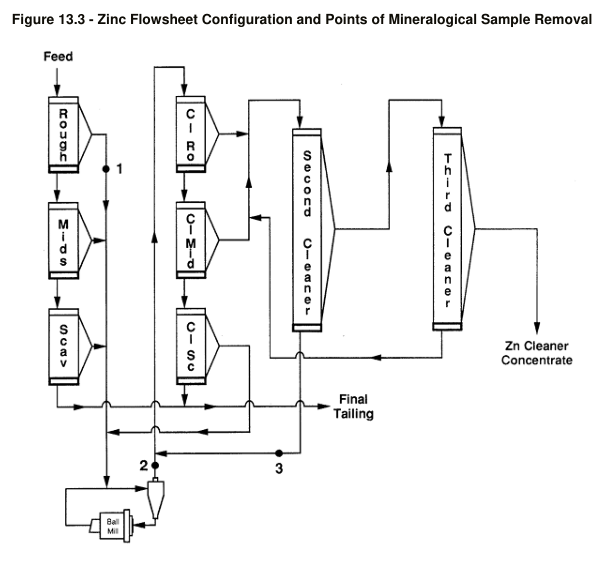
The zinc flotation circuit will include roughing and scavenging flotation stages, fed at a slurry density of 27% solids w/w, cleaning, cleaner scavenging, and two stages of recleaning. The conventional flotation circuit will be used to recover zinc minerals, with the rougher feed from the copper circuit tails. The zinc concentrate will be reground to a nominal circuit P₈₀ size of 38 µm, with test work indicating this grind size is optimal for maximising final zinc grade while minimising penalty elements.
Concentrate thickening and filtration
Dedicated high rate thickeners have been selected to thicken the copper and zinc concentrates. Thickener underflow at design slurry density of 60% solids w/w will be screened ahead of slurry reporting to each concentrate’s agitated filter feed tank.
Each concentrate filter feed tank will be agitated to keep solids in suspension, with a design total residence time of 24 hours. This will provide sufficient surge capacity for extended periods when either flotation circuits or downstream concentrate filters are offline for maintenance.
Dedicated horizontal plate and frame pressure filters have been selected as the final dewatering stage for both copper and zinc concentrates. The copper filter will have a design filter area of 20 m³. Due to higher zinc concentrate production rate, the zinc filter will have a design filter area of 160 m³. The filters have been sized to a design utilisation of 75%. The moisture content for both copper and zinc filter cake will be assumed to be less than 10%.
Each filter will discharge its filter cake onto its respective concentrate stockpile located below the filter. The concentrate building will have a design capacity of 2 days storage. Periodically, the front-end loader will batch load copper or zinc concentrate into 20 t top fill sea containers. Once fitted with the lid, the container will be weighed prior to being transported offsite. The process plant site will have a design capacity of 4 days for container storage.
Tailings disposal and paste backfill
A high-rate thickener has been selected to thicken the flotation tails stream to the design underflow density of 60% solids w/w. It is anticipated that 100% of the thickened tailings will be directed to the paste plant facility. However, if the paste backfill plant is offline for maintenance for an extended period, an option is provided to pump the tailings to the TSF.
The tailings thickener underflow will feed the agitated paste filter feed tank. The tank will be agitated to ensure solids are kept in suspension and will have a design total residence time of 12 hours. This will provide sufficient surge capacity for periods when either there is an interruption of slurry feed from the tailings thickener underflow or the paste fill plant is offline for maintenance.
Slurry will be pumped from the feed tank to two ceramic disc filters that will produce a filter cake having a target moisture content of 17%. The cake will be transferred by conveyor to a paste mixer along with binder. The paste will discharge into the paste hopper at approximately 78% solids w/w and will be pumped to underground. The paste plant has a design paste production rate of 448 m³/d.
Key reported parameters
| Description | Basis | Unit | Value |
|---|---|---|---|
| Annual Dry Ore Throughput | Nominal | t/a | 327,600 |
| Plant Feed Grade | Copper, Nominal | % | 0.78 |
| Plant Feed Grade | Zinc, Nominal | % | 16.25 |
| Recovery | Copper, Nominal | % | 78.4 |
| Recovery | Zinc, Nominal | % | 93.9 |
| Concentrate Grade | Copper, Nominal | % | 18.6 |
| Concentrate Grade | Zinc, Nominal | % | 51.0 |
| Grinding | Throughput, Nominal | t/a | 327,600 |
| Grinding | SMC Value (A*b) | , | 32.4 |
| Grinding | Utilisation, Design | % | 85 |
| Grinding | Feed Rate, Design | t/h | 44 |
| Grinding | Product Size P₈₀, Design | µm | 75 |
| Copper Rougher/Scavenger Flotation | Circuit Residence Time | Nominal | min |
| Copper Regrind | Concentrate Throughput | Design | t/h |
| Copper Regrind | Product Size P₈₀ | Design | µm |
| Copper Regrind | Regrind Mill Dimensions | Design | m |
| Copper Regrind | Regrind Mill Drive Power | Design | kW |
| Copper First Cleaner Flotation | Cells (3 x 3.3 m³) | Design | , |
| Copper First Cleaner Scavenger | Cells (2 x 3.3 m³) | Design | , |
| Copper First Cleaner + Scavenger | Residence Time | Design | min |
| Copper Conditioning | Residence Time (Conditioning Tank 1 + 2) | Design | min |
| Copper Concentrate Thickening | Feed Rate | Design | t/h |
| Copper Concentrate Thickening | Specific Settling Rate | Assumed | t/m².h |
| Copper Concentrate Filtration | Specific Filtration Rate | Design | t/m².h |
| Copper Concentrate Filtration | Filter Area | Design | m³ |
| Copper Concentrate Filtration | Filter Cake Moisture | Assumed | % |
| Copper Concentrate Filtration | Transportable Moisture Limit | Assumed | % |
| Zinc Flotation | Circuit Type | Design | , |
| Zinc Flotation | Feed Slurry Density | Nominal | % solids w/w |
| Zinc Regrind | Product Size P₈₀ | Design | µm |
| Zinc Concentrate Thickening | Feed Rate | Design | t/h |
| Zinc Concentrate Thickening | Specific Settling Rate | Design | t/m².h |
| Zinc Concentrate Filtration | Filter Area | Design | m³ |
| Zinc Concentrate Filtration | Specific Filtration Rate | Design | t/m².h |
| Zinc Concentrate Filtration | Filter Cake Moisture | Assumed | % |
| Zinc Concentrate Filtration | Transportable Moisture Limit | Assumed | % |
| Tailings Thickening | Feed Rate | Design | t/h |
| Tailings Thickening | Specific Settling Rate | Assumed | t/m².h |
| Paste Plant | Paste Production Rate | Design | m³/d |
| Paste Plant | Paste Density | Nominal | % solids w/w |
Project website: https://www.geologyontario.mndm.gov.on.ca/mndmfiles/mdi/data/records/MDI000000001530.html
Historical production forecast data (from Table 17.1 of the source report) indicate copper recoveries of 78.4% and zinc recoveries of 93.9% for all years of the forecast period, with copper concentrate grades varying between 18.6% and 24.2% Cu depending on year, and zinc concentrate grade varying between 54.7% and 60.1% Zn. Feed grades for the historical forecast covered copper from 0.46% to 0.96%, zinc from 10.03% to 18.68%, with gold and silver values also reported.
Technical qualifications
This section was prepared by DRA on the basis from the Superior Lake Bankable Feasibility Study (Project 24801-REP-GE-001) presented to Superior Lake Resources dated September 27, 2019, prepared by Primero.
The processing plant design criteria have been developed from both historical and current test work results, as reported in Section 13 of the source report. The plant design has used results from historical test work and the test work program. Design of the flotation circuits, regrind circuit, and thickening and filtration equipment is based on these test work programmes.
Several design parameters are based on assumptions rather than test work, including specific settling rates for the concentrate thickeners, filter cake moistures, and transportable moisture limits. Reagent schemes for the copper and zinc flotation circuits are based on standard industry practice for copper and zinc sulphide flotation. The crushing plant is to be provided and operated by an independent contractor. The paste plant design assumes a nominal density of 78% solids w/w for paste produced. The design of the plant has been based on well-proven unit operations, with a moderate level of instrumentation and automation.
Source: NI 43-101 Technical Report, Feasibility Study for the Superior Zinc and Copper Project, October 2021, Section 17 Recovery Methods, DRA Ref.: C5650 – Final Report, C5650-Metallum_NI43101_Final_20211014.
