

—
Standfirst
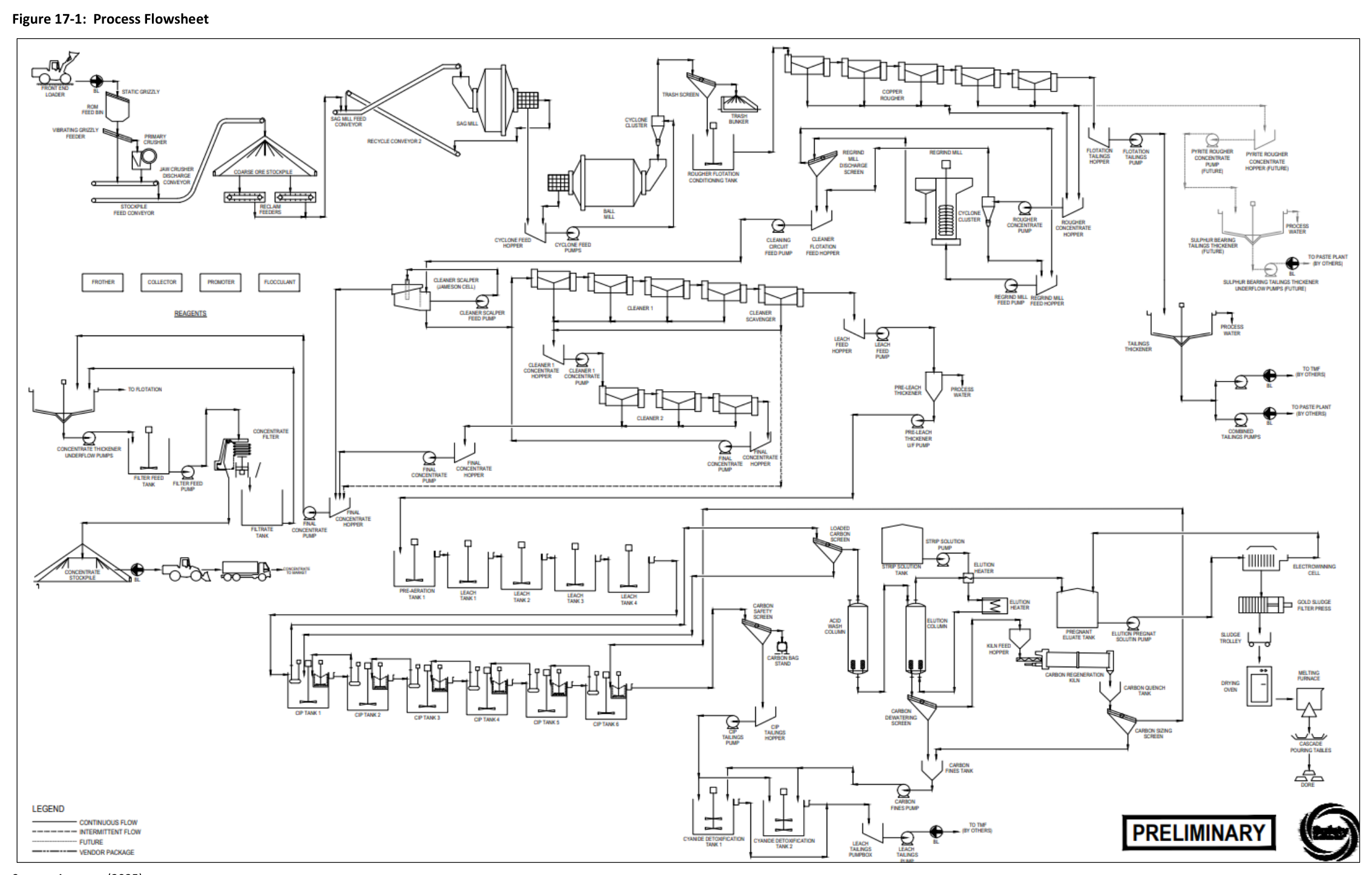
The process flowsheet proposed for the Green Bay Ming Mine project blends conventional flotation with a dedicated gold recovery circuit, and the design criteria selected for the plant show the results of preliminary metallurgical testwork.
—
The Green Bay Ming Mine Copper–Gold Project is an operating mine property located in Newfoundland, Canada, that has been in production under previous operators. The technical report supporting this review presents a preliminary economic assessment prepared for FireFly Metals Ltd., which operates the site under an EPA Certificate of Approval. The assessment was prepared in accordance with National Instrument 43-101 and the requirements of Form 43-101 F1, with the work conducted by independent engineering consultants and firms. The current mineral resource estimate for the Ming deposit is reported at a cut-off grade of 1% Cu, with the 1806 and 1807 gold-rich VMS domains reported using a 1% CuEq cut-off. The effective date of the mineral resource estimate is August 14, 2026. The project site hosts a mine that has been in operation, with historical production from the Nugget Pond milling facility having informed the metallurgical programs for the current study. The process plant design described in this article was selected based on preliminary testwork and subsequent economic modelling, and the route chosen is best suited to the recovery of copper and gold from mine production, with unit operations that are standard technologies typically used in concentrators and gold plants. The process flowsheet developed for the project includes crushing, grinding, flotation, regrind, concentrate handling, and a precious metals recovery circuit that uses leaching, adsorption, and electrowinning to produce gold–silver doré.
Process Design Criteria
The key process design criteria for the plant are listed in Table 17-1 of the technical report. The process plant design was chosen for optimum recovery of copper and gold in concentrate, and the design values represent the performance targets that the plant is expected to achieve on the design blend of ore. The annual process plant throughput is not disclosed in the source material, but the SAG mill feed conveyor is designed to withdraw material from the stockpile at a rate of 4,800 t/d to feed the grinding circuit. The Bond ball mill work index at the 80th percentile for the design blend is 11.5 kWh/t, and the SMC Test Axb value at the 25th percentile for the design blend is 50.1. The regrind mill is a vertical tower-style unit with a 1,500 kW motor, and the regrind specific energy is 11.3 kWh/t. The cyclone overflow is targeted at a grind size of 38 µm, which is the design value for the flotation feed.
The flotation circuit is designed around a series of recovery stages, with each stage having its own design recovery value. The cleaner scalper flotation stage has a design copper recovery of 60% and a design gold recovery of 45%. The cleaner 2 flotation stage has a design copper recovery of 39% and a design gold recovery of 42%. These are design values, which are distinct from the results of metallurgical testwork, and they represent the performance that the plant is expected to achieve under the specified design conditions. The pre-leach unit area thickening rate is 0.35 t/m²/h, and the concentrate unit area thickening rate is also 0.35 t/m²/h. The concentrate thickener underflow pulp density is specified, and the design criteria include the regrind specific energy noted above.
Water requirements were estimated at 10.3 m³/h for the process plant operation. The total estimated maximum power demand for the process plant is 10.7 MW, with a breakdown per area summarized in Table 17-3 of the report. The power demand figures represent the maximum expected demand, not the nominal or average operating demand, and they are presented as total values for the complete process plant.
Grinding and Flotation
Two reclaim apron feeders withdraw material from the stockpile to the SAG mill feed conveyor at a rate of 4,800 t/d to feed the grinding circuit. The cyclone overflow passes through a trash screen and then reports to a conditioning tank ahead of the rougher flotation cells. Gravity scalping in the rougher feed duty was not included in the process plant design at the time of writing, and this is noted in the technical report as a departure from the metallurgical testwork program described elsewhere in the document. The rougher flotation area includes a bank of conventional flotation cells, and the rougher concentrate reports to the regrind circuit for further liberation of the sulphide minerals.
The regrind circuit includes a regrind cyclone cluster with 250 mm diameter units, a vertical tower-style regrind mill with a 1,500 kW motor, and a discharge screen feeding a cleaner scalper that uses a high shear flotation cell. The cleaner scalper produces a final concentrate, which is then processed through the concentrate handling circuit. The cleaner circuit includes a single stage of flotation, with the cleaner 2 flotation stage providing an additional recovery stage for copper and gold. The concentrate filtration area includes a filter that dewaters the concentrate for transport off-site. The dewatered concentrate is stockpiled and loaded into covered trucks for transport off-site, and a section of the concentrate filtration and storage area is shown in Figure 17-11 of the technical report. A section of the regrind area is shown in Figure 17-6, and the grinding area section is shown in Figure 17-4.
Precious Metals Recovery
The precious metals recovery circuit uses a conventional leach–adsorption–detoxification process to recover gold and silver from the flotation tailings and concentrates. The leach circuit operates in a counter-current configuration, with the pregnant solution passing through a series of adsorption tanks containing activated carbon. The loaded carbon is transferred to the elution column, where the gold and silver are stripped from the carbon using a desorption process. The pregnant solution is then processed through electrowinning and the gold room, where the gold and silver are recovered by electroplating onto stainless steel cathodes.
The sludge from the electrowinning circuit is filtered, dried, mixed with fluxes, and smelted in an electric induction furnace to produce gold–silver doré as shown in Figure 17-10 of the technical report. The electrowinning and smelting process takes place within a secure and supervised gold room, with appropriate ventilation, fire, safety protection, eyewash stations, and safety data available. The gold room is designed to provide a secure environment for the handling of precious metals, and the smelting process uses an electric induction furnace, which is a standard technology used in gold plants.
The leach–adsorption–detoxification area section is shown in Figure 17-8, and the process flowsheet is shown in Figure 17-1. The process plant design criteria for the precious metals circuit include the leach circuit recovery rates, which are not disclosed in the source material. The gold recovery model for the precious metals doré is shown in Figure 1-5 of the technical report, and this figure presents the recovery model that was used for the economic assessment.
Tailings Management and Water Systems
The tailings thickener underflow is pumped to the tailings management facility or the paste plant, and the tailings dewatering circuit includes a thickener that produces a thickened underflow for disposal. At this time, the pre-leach thickener tailings hopper and thickener are repurposed within the process flowsheet, which is a design decision that reuses existing equipment for the tailings dewatering duty. The tailings thickening section is shown in Figure 17-12 of the technical report.
Process water is managed through a series of systems that recover water from the tailings thickener overflow, the concentrate thickener overflow, and other process streams. The process water is returned to the plant and stored in a process water tank, and gland seal water for the plant is sourced from the process water tank and filtered via sand filter, then pumped to the users throughout the process plant. Raw water is supplied to the plant for make-up duty, and fire and potable water systems are provided for safety and domestic use. Water and air services are provided for the process plant utilities, and the raw water, fire water, and potable water systems are designed to meet the demands of the plant.
Additional Interesting Data and Summary
The process plant design includes a number of specific design decisions that are notable in the context of the project's development. The decision to repurpose the pre-leach thickener tailings hopper and thickener within the process flowsheet is a design choice that reduces the amount of new equipment required for the tailings management circuit. The process plant design does not include gravity scalping in the rougher feed duty, which was tested as part of the metallurgical program but was not included in the plant design at the time of writing.
The reagent consumption summary in Table 17-2 of the technical report lists the types of reagents, their uses, and annual consumptions for an average annual VMS/LFZ blend feed. The reagent consumption values are presented for the average annual blend, which represents the expected feed composition over the life of the mine, and they include flotation reagents, leach reagents, and flocculant usage. The grinding area section is shown in Figure 17-4 of the technical report, and the regrind area section is shown in Figure 17-6.
The process design criteria include the design recovery values for the flotation stages, which are distinct from the metallurgical testwork results that informed the design. The design recoveries are the performance targets that the plant is designed to achieve, while the testwork results represent the actual performance of the ore in laboratory or pilot-scale testing. The process plant design was selected based on preliminary testwork and subsequent economic modelling, and the design values are the basis for the equipment sizing and the plant configuration.
The plant is designed to treat a blend of ore from the VMS and LFZ domains, with the process flowsheet incorporating conventional flotation to produce a copper–gold concentrate and a dedicated precious metals recovery circuit to recover gold and silver from the flotation tailings. The precious metals circuit uses carbon-in-pulp technology for the adsorption of gold and silver from the leach solution, followed by electrowinning and smelting to produce doré. The process flowsheet includes cyanide detoxification to treat the leach residue prior to disposal in the tailings management facility.
The process plant has a maximum power demand of 10.7 MW, which is the total for all areas of the plant, and this value is presented in Table 17-3 of the technical report. The process and gland water system has an estimated demand of 10.3 m³/h, and the water and air services include the process plant utilities, such as the compressed air system and the water supply pumps. The process plant is designed to meet the environmental requirements of the site, including the cyanide detoxification circuit and the tailings dewatering system.
The design of the process plant includes several equipment areas that are shown in section views, including the crushing area, the stockpiling area, the grinding area, the regrind area, the flotation area, and the tailings thickening section. These figures are provided in the technical report to show the physical arrangement of the equipment and the general layout of the plant. The process flowsheet is shown in Figure 17-1, and the sections provide additional detail on the layout of the major process areas.
The process plant is designed to produce a final copper–gold concentrate that is dewatered by filtration and then transported off-site by covered trucks. The concentrate filtration area includes the filter press and the associated feed and discharge equipment, and the dewatered concentrate is stockpiled in a covered area before being loaded into trucks. The concentrate handling circuit is designed to minimize moisture content in the final product and to prevent any losses during transport.
The leach circuit is designed as a counter-current process, with the carbon being transferred from tank to tank in the opposite direction to the slurry flow. This counter-current configuration continues until the loaded carbon reaches the first CIP tank, where it is removed from the circuit and sent to the elution column. The pregnant solution pump has the option to bleed barren solution to the leach circuit, which provides operational flexibility for the control of the solution grade and the recovery of gold.
The process plant is designed to meet the requirements of the project's environmental permits and the applicable regulations, including the management of process water and the treatment of tailings. The water management system includes a return water system from the tailings thickener overflow, the concentrate thickener overflow, and surface contact water. The process water system is designed to minimize fresh water consumption by maximizing the recycle of process water within the plant.
The process design criteria and the equipment selection have been established based on the results of the metallurgical testwork program and the engineering studies that support the preliminary economic assessment. The process plant design is the basis for the capital and operating cost estimates included in the PEA, and the performance of the plant is projected based on the design criteria and the testwork results.
Source: NI 43-101 Technical Report and Preliminary Economic Assessment of the Green Bay Ming Mine Copper–Gold Project, September 22, 2026. Project website: Green Bay Ming Mine Copper-Gold Project
Consolidated report summaries
The following former standalone pages about this operation were consolidated here on October 25, 2026. They are retained for source traceability; dates and figures reflect each report’s own effective date and may be superseded by the current information above.
Ming Copper-Gold Mine — 2018 Technical Report
This section describes the recovery methods for the Ming Copper-Gold Mine project, which will use the existing Nugget Pond concentrator as-is without modifications, and details the process design criteria, reagent systems, and plant availability assessment.
The recovery of a copper-gold concentrate from the Ming Mine is based on using the existing copper concentrator located at Nugget Pond. The existing grinding and flotation circuits, and concentrate dewatering equipment will be used as-is without any modifications. Run-of-mine (ROM) mill feed from the Ming Mine is stored on an outdoor pad at the Nugget Pond site. It is fed through a two-stage crushing plant by front-end loader and the crushed material is conveyed into the crushed ore silo. From there, the ore is processed through the grinding and flotation circuits to produce a copper-gold concentrate, which is then dewatered and transported by truck to the Goodyear's Cove Port Site for shipment.
The process design criteria and operating parameters for the concentrator are based on historical operating data from the Nugget Pond operations during 2016 and 2017, as well as bench test results. The concentrator design capacity is 1,250 tonnes per day of ROM mill feed when running continuously 24 hours per day. The annual availability at design capacity is 95%, based on average Nugget Pond operations from January 2016 to November 2017, where the availability factor is calculated as the total number of hours the mill was reported to be operating in a given month divided by the total number of hours in the month. Days when the mill was shut down due to a lack of ore from the mine were not counted against plant availability, as this was an issue of lack of feed rather than the availability of the mill.
Critical Data
| Parameter | Value | Unit | Notes |
|---|---|---|---|
| Concentrator design capacity ROM mill feed throughput | 1,250 | tonne/d (dry) | When running continuously 24 hours per day |
| Concentrator annual availability at design capacity | 95 | % | Total availability over 365 days for design purposes. Based on average Nugget Pond operations from January 2016 to November 2017 |
| Crushed ore top size | 12.7 | mm | Feed to SAG mill |
| Ground ore 80% passing particle size | 120 | micron | Grind size achieved based on plant data for operation at 1,250 tpd |
| Average overall copper recovery to concentrate | 96.0 | wt% | Based on average Nugget Pond mill data 2016 and 2017 |
| Copper concentrate grade dry basis | 27.7 avg., 25.0 min., 30.0 max. | wt% Cu | Based on average Nugget Pond mill data 2016 and 2017 and typical range from Nugget Pond operations and bench test results |
Overview
The Ming Copper-Gold Mine project will utilize the existing copper concentrator located at Nugget Pond for the recovery of a copper-gold concentrate. The existing grinding and flotation circuits, and concentrate dewatering equipment will be used as-is without any modifications. The concentrator has a design capacity of 1,250 tonnes per day of ROM mill feed and operates with an annual availability of 95% at design capacity, based on historical operating data from 2016 and 2017. The process design criteria are summarized in Table 17.1 of the technical report and include a crushed ore top size of 12.7 mm, a ground ore 80% passing particle size of 120 microns, an average overall copper recovery to concentrate of 96.0 wt%, and a copper concentrate grade ranging from 25.0 wt% Cu minimum to 30.0 wt% Cu maximum, with an average of 27.7 wt% Cu.
The concentrator uses a programmable logic controller (PLC) based process control system for the existing grinding circuit and the flotation plant. The control of the new process water reclaim pumps at Camp Pond and The Steady will be integrated into the PLC control system in the grinding area. The future operation will use a new process water reclaim pump house located at Camp Pond, which will eventually be relocated to The Steady later in the operation. Process water reclaim from the tailings impoundment areas will provide all of the process water required for the concentrator.
Key Process Stages
The process flow for the Ming Copper-Gold Mine recovery operations consists of several key stages: crushing, grinding, flotation, concentrate dewatering, and concentrate transport. Run-of-mine mill feed is stored on an outdoor pad and fed through a two-stage crushing plant by front-end loader, with the crushed material conveyed into a crushed ore silo. The material is then fed to a semi-autogenous grinding (SAG) mill, with a minimal amount of oversize material from the SAG mill trommel screen collected in a bin and periodically dumped back on the mill feed stockpile. The ground material from the grinding circuit is received in a flotation feed holding tank, which provides surge capacity and allows downstream processes to continue operating during short-term interruptions of the grinding circuit.
The flotation circuit consists of rougher, rougher-scavenger, cleaner, cleaner-scavenger, secondary cleaner, and tertiary cleaner stages. Flotation collector (Aerophine 3418A) and additional lime are added to the flotation feed holding tank to adjust the pH to the optimum range for copper-gold recovery and pyrite rejection. The ground material is pumped from the flotation feed holding tank to the rougher conditioning tank, where more conditioning time is provided and MIBC frother is added. Under certain conditions, the rougher concentrate grade from the first cells in the bank may be suitable as final concentrate, and the operator may direct this stream via the outside launder to the concentrate handling system. Additional 3418A collector and MIBC frother are added to the rougher-scavenger feed box, as these cells are designed to maximize recovery of copper and gold from the rougher tailings.
The concentrate from the primary cleaner stage is routed to the secondary cleaner stage, and the secondary cleaner concentrate is routed to the tertiary cleaner stage, from where the final concentrate product is directed to the concentrate dewatering system. Cleaner-scavenger concentrate is recycled to the cleaner conditioning tank, and tailings are routed to the rougher-scavenger flotation cell feed to scavenge additional copper and gold. The rest of the feed to the cleaner conditioning tank consists of rougher concentrate, cleaner-scavenger concentrate, and secondary cleaner tails, all of which are conditioned once again with lime and 3418A collector prior to being fed to the cleaner circuit. Hydrated lime slurry is added to the cleaner-scavenger, secondary cleaner, and tertiary cleaner feed boxes to maintain the optimum pH for copper-gold upgrading throughout the cleaner circuit, and additional 3418A collector and MIBC frother are added to the cleaner-scavenger feed.
Concentrate dewatering involves thickening and filtration. The concentrate is processed through a thickener, with the supernatant directed to the process water tank, and a filter press to achieve the required moisture content. The dewatered copper concentrate is then loaded into trucks and transported 142 km from the Nugget Pond site to the Goodyear's Cove Port site, where a truck dump station, concentrate storage building, and boat loading equipment are used to load ocean-going bulk carriers for final shipment.
Additional Interesting Data and Summary
The operating history of the Nugget Pond concentrator for the last two years was reviewed to evaluate the average processing plant availability. The availability factor is calculated as the total number of hours the mill was reported to be operating in a given month divided by the total number of hours in the month. In a few of the months, the mill had to be shut down temporarily as there was no ore available from the mine to process. These days were not counted against the plant availability since it was an issue of lack of feed rather than the availability of the mill. The typical plant availability factor was determined to be 95% based on the average over the operating period. One shutdown was required to install new equipment related to operating the plant at the increased 1,250 tpd capacity.
The reagent systems for the concentrator include Aerophine 3418A collector, MIBC frother, hydrated lime, zinc sulphate, and AERO MX983. Aerophine 3418A collector is a copper-gold collector reagent supplied in liquid form by Cytec Solvay and is purchased in 1000-litre tote tanks. MIBC frother is purchased in 200-litre steel drums and is not miscible with water, so it is best fed to the flotation process neat. Dry powdered hydrated lime (calcium hydroxide) is supplied in 1-tonne bulk bags and is mixed in batches to the required 5 to 10 wt% concentration for distribution to the process. A hydrated lime slurry makeup and distribution system is used to supply lime to various unit operations within the copper concentrator building, and a separate similar system is used within the grinding area. Zinc sulphate solution is metered into the flotation feed holding tank when needed. The scavenger flotation collector AERO MX983 is received in liquid form in drums and is delivered to the process via a diaphragm metering pump pumping directly from the drum.
Tailings will be disposed of by pumping in slurry form to existing and new tailings impoundment areas to be developed adjacent to the Nugget Pond mill site. New tailings slurry distribution piping will be installed to suit the tailings disposal plan. The site location and infrastructure associated with process water reclaim is described in Section 18 of the technical report.
Key Processes
- Two-stage crushing plant fed by front-end loader, with crushed material conveyed to a crushed ore silo
- Semi-autogenous grinding (SAG) mill and ball mill circuit with trommel screen oversize recycle
- Flotation feed holding tank providing surge capacity and pH adjustment with Aerophine 3418A collector and lime
- Rougher and rougher-scavenger flotation cells designed to maximize copper and gold recovery
- Cleaner, cleaner-scavenger, secondary cleaner, and tertiary cleaner flotation stages for concentrate upgrading
- Concentrate dewatering using a thickener and filter press
- Truck transport of concentrate 142 km from Nugget Pond to Goodyear's Cove Port Site for boat loading
- PLC-based process control system for grinding circuit, flotation plant, and new process water reclaim pumps
- Process water reclaim from tailings impoundment areas providing all process water requirements
- Tailings disposal by slurry pumping to existing and new tailings impoundment areas
Source: Ming Copper-Gold Mine , 2018 Technical Report, 2018. Project website: Rambler Metals & Mining Canada Limited (https://www.gov.nl.ca/eccc/projects/project-1487/)
Project website: Ming Copper-Gold Mine, 2018 Technical Report
