

The Borborema Gold Project is a feasibility-stage project located 26 km east of Currais Novos in Rio Grande do Norte, northeastern Brazil. Owned by Aura Minerals Inc., the project targets gold mineralization hosted in biotite-garnet schist within a sheared orogenic gold deposit. The technical report supporting the feasibility study carries an effective date of December 31, 2025, with the technical report dated May 25th, 2026. Construction timing is not stated in the recovery methods section of the report.
Critical Data
| Parameter | Value | Unit | Notes |
|---|---|---|---|
| Nominal plant throughput | 2.0 | Mtpy | Design value |
| Crushing circuit throughput | 304.4 | t/h | Design value |
| Crushing circuit availability | 75 | % | Design value |
| Grinding circuit availability | 90 | % | Design value |
| Nominal head grade | 1.22 | g/t | Design value |
| Gravity recovery gold (GRG) | 20 | % | Design value |
| Leach/CIL recovery gold | 90.1 | % | Design value |
| Global gold recovery | 92.1 | % | Design value |
| Crusher feed size F80 | 319.5 | mm | Design value |
| Crushing circuit product P80 | 122 | mm | Predicted from simulations |
| Grinding product P80 | 0.105 | mm | Design value |
| SAG mill installed power | 8,000 | kW | Design value |
| Plant JD jktech UCS 85th | 40.2 | MPa | Design value |
| JKTech BWi 85th | 18.1 | kWh/t | Design value |
| ROM top size | 700 | mm | Design value |
| Total leach residence time | 30 | h | Design value includes pre-leach and CIL |
| Number of leach/CIL tanks | 7 | Not applicable | 1 leach tank plus 6 CIL tanks |
| CIL carbon concentration | 16 | g/L | Design value |
| Detox CNwad target | <1 | mg/L | Design value from 63.4 mg/L feed |
| SAG mill dimensions | 7.9 x 7.0 | m | Diameter x effective grinding length |
| SAG mill motor | 8 | MW | Installed power |
| Hydrocyclone diameter | 500 | mm | 5 units |
| Gravity concentrator | KC QS40 | Not applicable | Or equivalent |
| Elution type | Zadra under pressure (ZP) | Not applicable | Batch operation |
| Elution batch size | 6 | t | Design value |
| Elution frequency | 5 | strips/week | Design value |
| Natural moisture | 3.0 | % | Design value |
| JKTech Ai 85th | 0.123 | g/t | Abrasion index design value |
| JKTech SG 85th | 2.8 | t/m³ | Design value |
| Thickener underflow density | 54 | % solids w/w | From detox tailings thickener |
| Filter cake moisture | 20-21 | % | Design value from horizontal vacuum belt filters |
Overview
The Borborema processing plant was designed from metallurgical test work combined with industry best practices for gold recovery. The ore body contains gold distributed from relatively coarse to fine grained material. Test work results supported a flowsheet that includes gravity concentration followed by cyanidation. The carbon-in-leach approach was selected because metallurgical testing showed adequate extraction and kinetics.
Gold characterization work identified that a high concentration of gold occurs in coarse particles. The metallic screen fire assay technique provided reasonable consistency for determining head contents. Ten variability leaching tests produced gold extraction ranging from 90.2% to 97.9% with residues between 0.01 and 0.28 g/t Au. Reagent consumption remained low across all tests, with average cyanide consumption of 0.24 kg/t and lime consumption of 0.46 kg/t. These results align with consumption observed in master composite testing.
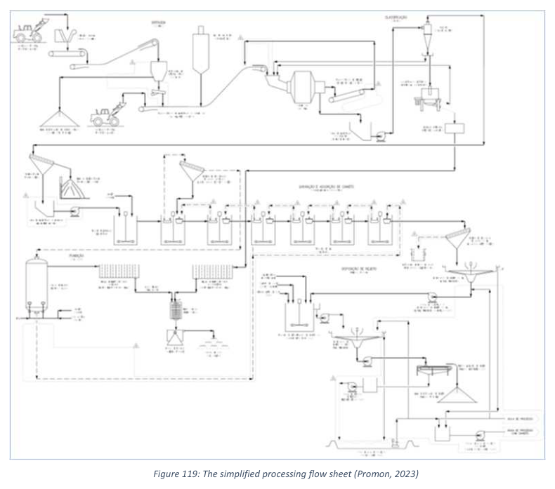
The flowsheet accommodates the circuit capacity through a sequence of primary crushing, crushed ore stockpiling, single-stage grinding with hydrocyclone classification, gravity concentration, and cyanidation in a CIL circuit. After leaching, the pulp undergoes thickening to recover cyanide-bearing water for recirculation. Cyanide neutralization uses the INCO process with air and sulfur dioxide in the presence of copper sulfate catalyst. Lime milk adjusts pH. The detoxified slurry is thickened again, filtered, and sent to dry stacking tailings disposal.
Key Process Stages
The crushing circuit starts with run-of-mine material hauled and dumped in stockpiles. Front-end loaders reclaim material into the crushing feed hopper equipped with a static grizzly at 0.7 m aperture. A mobile rock breaker handles oversize rocks. A vibrating grizzly feeder controls the feed rate at 304 t/h nominal throughput. The grizzly separates coarse and fine fractions. Coarse material flows to the primary jaw crusher. Fine material combines with crusher discharge and is conveyed to a surge bin. The crushing and milling circuits operate at different availabilities, so excess crushed material accumulates in a dedicated stockpile when the crushing plant runs fully. Front-end loaders reclaim material from the stockpile to a reclaim bin with a vibrating feeder that supplies the milling circuit. The predicted crushing circuit product P80 is 122 mm.
The grinding circuit uses a single-stage semi-autogenous mill in closed configuration with hydrocyclones. Fresh feed from the surge bin goes to the SAG mill. Discharge pulp flows to a trommel screen. Pebbles retained on the trommel go back to the SAG mill feed. Trommel undersize gravitates to a sump and is pumped to a nest of five hydrocyclones at 500 mm diameter each. Cyclone underflow splits into two streams. One stream goes through the gravity concentration stage, and its tailings return to the SAG mill feed. The other stream goes directly back to the SAG mill feed. Cyclone overflow is the grinding circuit product. Water addition at the SAG mill feed and sump adjusts pulp dilution to 72% and 60% w/w respectively. Hydrocyclone overflow at 35% solids w/w goes to a trash screen, with undersize feeding the CIL circuit. The SAG mill measures 7.9 m in diameter by 7.0 m effective grinding length and is powered by an 8 MW electric motor.
The gravity concentration circuit has one centrifugal concentrator with a feed scalping screen. Feed comes from the cyclone underflow to the scalping screen. Oversize material at plus 2 mm goes to the gravity tails pump box and returns to the SAG mill feed. Scalping screen undersize feeds the centrifugal concentrator. The gravity concentrator operates in semi-batch mode. Gravity concentrate collects in a storage cone, then is leached in the intensive cyanidation reactor circuit. Gravity concentrator tails also report to the gravity tails pump box.
The intensive leaching reactor treats gravity concentrate for gold extraction by intensive cyanidation. Concentrate from the gravity concentrator goes to the ILR storage cone and is deslimed before transfer. Leach solution is prepared in a heated ILR feed tank. The solution circulates through the reaction vessel and drains back to the feed tank. Leached residue in the reaction vessel is washed. Wash water goes to the feed tank. Solid gravity leach tailings are pumped to the CIL circuit. Pregnant leach solution from the ILR feed tank goes to a pregnant solution tank in the gold room. There it is treated in a dedicated electrowinning cell to produce gold sludge. That sludge combines with sludge from the carbon elution electrowinning cells and is smelted. The ILR gold sludge can also be smelted separately for metallurgical accounting.
The CIL circuit receives trash screen undersize material. The circuit has one leach tank and six carbon-in-leach tanks. Air is sparged into each tank to maintain dissolved oxygen for leaching. Hydrated lime adjusts pH to the required set point. Cyanide solution is added to the first leach tank. Mechanical agitation keeps solids suspended and reagents homogenized. Fresh carbon and carbon from regeneration are added to the last CIL tank at an average concentration of 16 g/L of pulp. Carbon flows counter-currently to the slurry. Slurry from the last CIL tank gravitates to the cyanide detoxification tanks. Once per day, pulp from the first carbon tank is pumped to a screen for separating loaded carbon from pulp. Loaded carbon goes to acid washing and elution. After regeneration, carbon returns to the circuit through a dewatering screen.
Post-leach tailing thickening uses a high-rate thickener designed for the annual production plan. Flocculant is added at 40 g/t in the thickener feedwell. Thickener overflow recirculates to the grinding circuit. Underflow is pumped to the Detox circuit.
The cyanide neutralization system reduces weak acid dissociable cyanide from 63.4 mg/L to less than 1 mg/L. Two tanks each provide 60 minutes residence time. The process uses the SO2/air method. Required reagents are sodium metabisulfite as the SO2 source, copper sulfate pentahydrate as the catalyst, and hydrated lime for pH and oxidation-reduction potential control. Air is injected through spargers. Agitators ensure thorough mixing.
The detox tailings thickener is high-rate equipment. Neutralized tailings slurry is thickened to recover cyanide-free process water for operations where cyanide is not compatible. The second neutralization tank pumps pulp at 45% solids w/w. Thickener overflow goes to the raw water tank. Underflow at 54% solids w/w is pumped to the filtering system.
The filtering circuit includes three horizontal vacuum belt filters. A dedicated tank equalizes daily operation between grinding, leaching, thickening, and filtering circuits. Filter cake moisture is reduced to 20-21%. Filtering water and thickening water recirculate within the plant. Filtered product goes to disposal piles. Runoff from piles also recirculates.
The elution circuit recovers adsorbed gold from activated carbon using a ZADRA process under pressure in batch operation. Loaded carbon transfers from the carbon screen to the acid washing column. A 3% w/w hydrochloric acid solution is injected at the bottom of the elution columns at 2.2 bed volumes per hour. Carbon is washed and diluted acid is neutralized with 10% w/w caustic soda at 4 bed volumes. The eluate solution is heated to 90 degrees Celsius. The eluate solution is prepared at 1% sodium hydroxide and 0.1% sodium cyanide, heated to 110 degrees Celsius, and injected at 2 bed volumes per hour to the bottom of the elution column at 300 kPa pressure. The eluted solution goes to the pregnant solution tank for electrowinning. Solution recirculates to the eluate tank through heat exchangers. Carbon is cooled with raw water and transferred to the last CIL tank. At the end of each elution cycle, one third of the electrowinning barren solution is transferred to the CIL circuit.
The gold room processes sludge from gold-rich cathodes. Cathodes are washed, filtered, and dried. The dry material is mixed with smelting fluxes including borax, nitrate, carbonate, and silica. Smelting occurs in a liquefied petroleum gas furnace at 1,100 degrees Celsius to produce gold doré bullion.
Additional Interesting Data and Summary
The conclusions in the recovery methods section note that the Borborema processing plant is similar to several industrial operations in the gold mining industry. The wastewater processing from the city of Currais Novos requires additional testing and further engineering work. Risks to raising capital include additional investment for new sewage receiving lines. Possible capital reductions could come from simplifying the water treatment plant if the accumulation of water in rainy seasons proves consistent and reliable. The single recommendation for further assessment is on water supply alternatives.
The water system has two ponds. One pond stores raw water with 5,300 cubic meters capacity. The other pond stores recycled water without cyanide at 3,000 cubic meters capacity. The main raw water source is wastewater from the Currais Novos sewage pumping station, pumped at 83 cubic meters per hour through a pipeline to the water treatment plant. Rainwater dammed in the fines dike provides a reserve supply. The water treatment plant includes filtration, chlorination or UV disinfection, and reverse osmosis.
Potable water is supplied by tank truck at an average of 30 cubic meters per day. A 100 cubic meter tank serves the administrative areas. A water tower supplies operational areas. The potable water system includes a main supply ring to safety showers around the plant with continuous water return to prevent heating from stagnant water in pipes exposed to the sun.
Key Processes
- Primary jaw crushing of run-of-mine ore to a predicted P80 of 122 mm
- Single-stage semi-autogenous grinding with hydrocyclone classification to a product P80 of 0.105 mm
- Gravity concentration using a centrifugal concentrator with scalping screen
- Intensive cyanidation leaching of gravity concentrate in a dedicated reactor
- Carbon-in-leach cyanidation with one leach tank and six CIL tanks for total 30 hours residence time
- High-rate thickening of CIL tailings to recover cyanide-bearing water for recirculation
- Cyanide detoxification using the SO2/air INCO process with copper sulfate catalyst
- High-rate thickening of detoxified tailings to recover cyanide-free process water
- Horizontal vacuum belt filtration to reduce cake moisture to 20-21%
- Acid washing and Zadra pressure elution of loaded carbon
- Electrowinning and gold room smelting to produce doré bullion
- Dry stacking of filtered tailings with water recirculation from disposal piles
Source: Technical Report (NI 43-101) on the Feasibility Study for the Borborema Gold Project, Currais Novos Municipality, Rio Grande do Norte, Brazil, May 25th, 2026. Project website: Borborema Gold Project
