

Standfirst: The planned 4,900 tpd operation in east-central Saskatchewan will use SAG milling, sequential flotation, and paste backfill to produce separate copper and zinc concentrates for sale.
The McIlvenna Bay Project is a copper-zinc mine located in east-central Saskatchewan, approximately 375 km northeast of Saskatoon and 85 km west of Flin Flon, Manitoba. The site is accessible year-round via an 18 km all-weather road connected to Saskatchewan Provincial Highway 106. The 2025 Technical Report describes a proposed decline and shaft underground mining operation using long-hole mining methods for ore extraction at a nominal 4,900 tpd Phase 1 Operation. The project is owned by Eldorado Gold Corporation through its wholly owned subsidiary Foran Mining Corporation, which holds the claims through McIlvenna Bay Operating Ltd. As of April 14, 2026, Foran operates as a wholly owned subsidiary of Eldorado. Ore is expected to be processed using conventional single stage crushing with a SAG mill and ball mill design, followed by grinding and flotation circuits to produce both copper and zinc concentrates for transportation from site to Flin Flon for shipment by rail to Canadian smelters and/or offshore. There has been no mineral production on the McIlvenna Bay Project to date. The Technical Report's Phase 1 operation includes a 4,900 tpd underground mine, on-site crushing and mineral processing facilities, paste plant, filtered tailing storage facility, and supporting infrastructure such as water management and treatment facilities, offices, workshop, warehouse, mine dry, and first aid facilities.
Critical Data
| Parameter | Value | Unit | Notes |
|---|---|---|---|
| Nominal annual throughput | 1,788,500 | dmtpa | Design value |
| Nominal daily throughput | 4,900 | dmtpd | Design value |
| Operating hours per shift | 12 | h | Design value |
| Operating shifts per day | 2 | # | Design value |
| Operating days per week | 7 | d | Design value |
| Operating days per annum | 365 | # | Design value |
| Crushing circuit availability | 60 | % | Design value |
| Grinding circuit availability | 92 | % | Design value |
| ROM moisture | 4 | % | Design value |
| Abrasion index (62% CS Zone / 38% MS) | 0.256 | g | Design value |
| Rod mill work index (62% CS Zone / 38% MS) | 14.7 | kWh/t | Bond, metric |
| Rod mill work index (CS Zone) | 17 | kWh/t | Bond, metric |
| Rod mill work index (MS) | 12.7 | kWh/t | Bond, metric |
| Ball mill work index (62% CS Zone / 38% MS) | 16.5 | kWh/t | Bond, metric |
| Ball mill work index (CS Zone) | 17.9 | kWh/t | Bond, metric |
| Ball mill work index (MS) | 13.7 | kWh/t | Bond, metric |
| Plant feed blend of CS Zone ore, average | 62 | % | Design value |
| Plant feed blend of MS ore, average | 38 | % | Design value |
| Blended plant feed grade Cu | 1.27 | % | Design value |
| Blended plant feed grade Pb | 0.21 | % | Design value |
| Blended plant feed grade Zn | 3.64 | % | Design value |
| Blended plant feed grade Au | 0.56 | g/t | Design value |
| Blended plant feed grade Ag | 18.45 | g/t | Design value |
| Blended plant feed grade S | 13.75 | % | Design value |
| Crushing circuit feed F100 | 450 | mm | Design value |
| Crushing circuit product P100 | 245 | mm | Design value |
| Crushing circuit product P80 | 125 | mm | Design value |
| SAG mill feed F100 | 245 | mm | Design value |
| SAG mill feed F80 | 125 | mm | Design value |
| SAG mill discharge % solids | 75 | % | Design value |
| SAG mill pebble extraction | 30 | % | Design value |
| Transfer size | 1653 | µm | Design value |
| Ball mill discharge % solids | 73.6 | % | Design value |
| Ball mill circulating load | 300 | % | Design value |
| Cyclone overflow product P80 | 75 | µm | Design value |
| Cu flotation conditioning time required | 2 | min | Design value |
| Cu rougher residence time required | 20 | min | Design value |
| Cu rougher mass pull | 15 | % | Design value |
| Cu regrind mill product P80 | 25 | µm | Design value |
| Cu cleaner 1 residence time required | 20 | min | Design value |
| Cu cleaner 2 residence time required | 10 | min | Design value |
| Cu cleaner 3 residence time required | 7.5 | min | Design value |
| Zn flotation first conditioning time required | 6 | min | Design value |
| Zn rougher residence time required | 15 | min | Design value |
| Zn rougher mass pull | 25 | % | Design value |
| Zn regrind mill product P80 | 20 | µm | Design value |
| Zn cleaner 1 residence time required | 12.5 | min | Design value |
| Zn cleaner 2 residence time required | 10 | min | Design value |
| Zn cleaner 3 residence time required | 8.8 | min | Design value |
| Py rougher mass pull (total Jameson plus rougher cells) | 34 | % | Design value |
| Cu conc thickener U/F solids content | 55 | % | Design value |
| Zn conc thickener U/F solids content | 55 | % | Design value |
| Cu/Zn conc cake moisture | 9 | % | Design value |
| Py conc thickener U/F solids content | 60 | % | Design value |
| Py conc live storage | 2 x 3182 | m3 | Design value |
| Py conc average cake moisture | 18 | % | Design value |
| Paste plant availability | 50 | % | Design value |
| Split of mill feed to paste, design | 47 | % | Design value |
| Paste cement addition | Not stated | % | Table value missing from source |
| Non-sulphide tailings live storage | 2400 | m3 | Design value |
| Tailings thickener U/F solids content | 55 | % | Design value |
| Tailings average cake moisture | 15 | % | Design value |
| Average demand load, process plant | 18.4 | MW | Design value |
| Nominal raw water requirements | 42 | m3/h | Design value |
Overview
The process plant design for the McIlvenna Bay Project is based on a conventional metallurgical flowsheet to treat copper-zinc ore. The flowsheet draws on metallurgical test work described in Section 13 of the report, industry standards, and conventional unit operations. The two most prevalent mineralization types feeding the mill will be CS and MS. The CS Zone consists mostly of copper sulphide minerals in stringer type textures with minor amounts of zinc, and the MS contains higher zinc grades with additional copper units. The CS Zone material is harder and contains less pyrite than the MS zone.
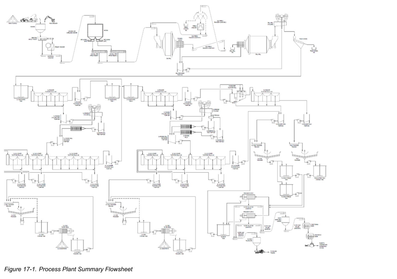
The plant consists of a comminution circuit followed by sequential copper and zinc flotation, with concentrate regrind and dewatering to produce both copper and zinc concentrates for sale. A pyrite flotation circuit will produce pyrite concentrate and tailings which will be dewatered and filtered for paste fill and tailings storage. The process plant spans several numbered areas, from Area 6100 (crushing) to Area 6800 (reagents).
The plant layout places equipment within one large mill building with a dedicated area for tailings filtration and paste production. The tailings thickeners and storage tanks will be located outdoors and partially clad to ensure effective operation in cold climates. A reagent storage area will be located along one side of the process plant building, with reagents stored and transferred to the reagent day tank and dosing area within the main building.
Key Process Stages
Run-of-mine ore will be hauled from underground or surface stockpiles to the primary crusher using a 50-t capacity haul truck or a front-end loader. The ROM stockpiles will be required to blend the various ore types to achieve targeted mill head grades. Ore dumped into a 50-t ROM bin will discharge onto a vibrating grizzly feeder. The vibrating grizzly oversize will feed a FJ 1000 primary jaw crusher, while the grizzly undersize bypasses the crusher and combines with the primary crusher product in the discharge chute before discharging onto the sacrificial conveyor. The sacrificial conveyor transfers the crushed ore onto a crushed ore overland conveyor that feeds the ore storage bin.
Crushed ore will be stored in a 12-hour, 2,500-t live capacity ore storage bin. The overland conveyor will be equipped with a metal detector to prevent tramp metal from entering the ore bin. Two variable-speed apron feeders draw down the ore bin in a controlled manner to feed the SAG mill feed conveyor, with two ore sliding gates available to isolate the ore feeding the apron feeders as required. A reclaim dust collector will draw from collection points around each apron feeder to mitigate dust buildup.
The grinding circuit includes a SAG mill in closed circuit with a pebble crusher and a ball mill, along with cyclone classification. Crushed ore sized at a P80 of 125 mm is conveyed from the ore bin to the mill building via the SAG mill feed conveyor, where the ore is combined with the pebble product and fed into the SAG mill. Process water maintains a 75% slurry density in the mill. The SAG mill is a 7.32 m diameter by 3.38 m EGL unit equipped with a 3,500 kW variable-speed drive. The steel charge consists of 125 mm balls at 7.6% to 16% of the chamber volume and a total load of steel and ore of 25%. Internal discharge grates use 25 mm slurry ports and 50 mm pebble ports. Slurry exits via a trommel screen with 8 mm by 25 mm slots. The trommel oversize is conveyed to feed a pebble crusher before being recycled back to the SAG mill feed conveyor, with an option to bypass the pebble crusher to an outdoor pebble bunker using a three-way divert chute. The trommel undersize reports to the mill discharge pump box together with the ball mill discharge.
The ball mill is a 5.03 m diameter by 7.85 m EGL unit equipped with a 3,500 kW variable-speed drive. The steel charge consists of 50 mm balls at 31% to 35% of the chamber volume. The ball mill is rubber-lined and fed with cyclone underflow, with the mill discharge reporting through a trommel screen with 10 mm by 30 mm slots before laundering to the mill discharge pump box. Slurry is diluted and pumped to a 7 by 400CVD10 hydrocyclone pack, with five operating and two stand-by units. The feed to the hydrocyclone has a densitometer, flowmeter, and pressure transmitter for monitoring and control of feed density, flow, and pressure. Hydrocyclone overflow gravitates to the trash screen prior to reporting to copper conditioning, while the coarser cyclone underflow gravitates to the ball mill retractable feed chute as ball mill feed. The design circulating load in the cyclone underflow varies based on ore hardness and is expected to be between 300% and 350% of primary mill feed tonnage. Grinding balls are added to the SAG and ball mills via a kibble bucket hoisted by overhead crane, with storage bunkers adjacent to the process building holding 125 mm balls for the SAG mill and 50 mm balls for the ball mill.
Copper flotation consists of separate rougher and cleaner flotation equipment with a regrind mill installed to process the rougher concentrate prior to cleaner flotation. Cyclone overflow gravitates from the trash screen through the copper feed sampler and into an agitated copper conditioning tank. The bank of copper rougher cells consists of four 50 m3, 75 kW tank cells, with flotation air supplied by blowers via a low-pressure manifold. Rougher concentrate flows by gravity to the regrind circuit, where it is pumped to two cyclones, one operating and one stand-by. The underflow reports to a 500 kW horizontal M1000 copper regrind mill which reduces the P80 of the low-grade copper rougher concentrate to 25 µm. First stage cleaner flotation is provided by six 11.4 m3, 22 kW tank cells with integrated concentrate launders. The second cleaner concentrate is collected from a bank of two 11.4 m3, 22 kW tank cells and pumped to the third copper cleaner circuit, where final stage copper cleaning is achieved via a bank of two 11.4 m3, 22 kW tank flotation cells. Copper final concentrate is collected prior to pumping to the copper concentrate dewatering circuit.
Zinc flotation is similar in design to the copper circuit and is fed with combined copper flotation tailings slurry. Tailings slurry is pumped from the copper circuit via a sample station into the first of two agitated conditioner tanks in series, with the first primarily for pH control and the second allowing reagent conditioning. The bank of zinc rougher cells consists of four 50 m3, 75 kW tank cells. The concentrate flows by gravity to the regrind circuit, where the zinc regrind cyclone feed pump pumps the slurry to three cyclones, two operating and one stand-by. Each mill feed pump box feeds a corresponding 500 kW horizontal M1000 regrind mill, with the discharge of both mills combined with the zinc cyclone overflow before reporting to the zinc cleaner circuit. The zinc regrind circuit reduces the P80 of the zinc rougher concentrate to 20 µm. First stage cleaner flotation uses four 10 m3, 22 kW tank cells with integrated concentrate launders. The second cleaner concentrate is collected from a bank of three 10 m3, 22 kW tank cells and pumped to the third zinc cleaner circuit, where final stage zinc cleaning is achieved via a bank of two 10 m3, 22 kW tank flotation cells. Zinc final concentrate is collected prior to pumping to the zinc concentrate dewatering section. The zinc first cleaner tails bypass the pyrite circuit and report directly to the pyrite rougher concentrate pump box.
Copper flotation concentrate is pumped through a sampler before entering a 6 m diameter high-rate concentrate thickener for controlled dewatering, while zinc flotation concentrate enters a 7 m diameter concentrate thickener. Both thickeners are equipped with rake lift, bed level detection, and bed mass monitoring. Thickener underflow is withdrawn at 55% solids concentration by peristaltic pumps and sent to agitated concentrate storage tanks, with the copper storage tank surge capacity approximately 10.5 hours and the zinc thickener concentrate storage tank surge capacity approximately 8.4 hours. Concentrate stored in the tanks is pumped to dedicated pressure filters, with filtrate directed to corresponding filtrate de-aeration chambers and filtrate tanks before being pumped back to the appropriate concentrate thickener for recycling. A dedicated cloth and core wash tank services both filter presses to allow high pressure washing of the filter cloth at the end of each cycle. Filter cake discharges from each press to the corresponding concentrate load out bay below, with a wall separating the two concentrates to prevent cross-contamination. A front-end loader loads concentrate into side-tipping trucks for transportation off-site, with trucks weighed and auger-sampled at the weighbridge prior to dispatch.
Zinc rougher tailings slurry is pumped to the pyrite rougher flotation circuit for tailings desulphurization. The pyrite flotation step ensures that the dry stack tailings facility contains material with no more than 0.5% sulphur, on average. A non-selective bulk sulphide collector reagent SIPX is added to encourage flotation of the remaining sulphide minerals. The zinc rougher tails are pumped to the pyrite cell 1 feed box, a Jameson cell, where the tails are combined with a recirculated fraction of the tails stream. The feed is pumped through cavitation downcomers in the cell, with air aspirated through intakes located in the downcomers and cavitated with the pumped slurry. Wash water is added to the top of the froth to clean the froth as required. The tails flow by gravity to a bank of conventional pyrite rougher cells consisting of three 50 m3, 75 kW tank cells. The sulphide concentrate produced is combined with the zinc first cleaner tailings, dewatered, and directed to the paste backfill circuit for incorporation into the backfill mixture and safe storage underground.
Tailings slurry from the final cell in the bank of pyrite roughers reports to a 16 m diameter tailings thickener for dewatering and dry stack tails production. Thickener overflow gravitates to the combined tails thickener overflow pump box, where it is pumped through in-line filters prior to reporting to the process water tank for re-use within the process. Thickener underflow slurry is pumped from the thickener cone at 55% w/w solids concentration to a non-sulphide tailings surge tank located outside. This tank is agitated and holds approximately 18.5 hours of thickened tailings production. Thickened slurry from the surge tank is pumped to pressure filters for further dewatering, with filter cake discharged via conveyors into a filtered tailings bin. The tailings bin discharges the filtered tailings into trucks for placement on the nearby dry-stack tailings storage facility. The non-sulphide filtrate gravitates to a combined filtrate tank, from which it is pumped back to the pyrite concentrate thickener as feed dilution water.
Pyrite concentrate thickener underflow slurry is pumped from the thickener cone at 60% w/w solids concentration to two pyrite concentrate storage tanks located outside. These tanks are agitated and can hold approximately 72 hours of thickened pyrite concentrate to allow for time when paste backfill cannot be received underground. Pyrite concentrate slurry from the storage tanks is pumped to pressure filters for further dewatering, with filter cake discharged via a collector conveyor and incline conveyor into the paste plant. Dewatered pyrite filter cake enters a conditioning mixer with trim water to prepare the filter cake. The filter cake mixture is gravity-fed into a continuous mixer where it is mixed with binder to create cemented paste backfill. The paste is gravity-fed through the paste hopper to the paste pumps in a duty and future configuration. Binder delivery trucks add binder to the binder storage silo, which is equipped with a dust collector and rotary feeder that loads the binder onto a weigh belt feeder followed by a screw conveyor.
Plant services include plant and instrument air provided by four compressors. Three main compressors, two duty and one standby, feed a main distribution header. Two large plant air receivers fed from the main header act as buffer capacity due to large air requirements for the tailings filter presses. Concentrate filters are fed directly from the main header as no buffer capacity is required. Instrument air is provided from the main header after pressure regulation and fed through an instrument air dryer. A fourth smaller air compressor provides instrument air needed in a power outage to maintain control of instruments. Air compressors, including mine units, are cooled through a dedicated glycol-based heat recovery system, with recovered heat feeding the main HVAC system during winter. Low-pressure flotation air is supplied by two sets of blowers, three for the rougher flotation cells with two operating and one standby, and two for the cleaner flotation cells with one operating and one standby.
Water conservation measures will be implemented at the processing facility. Process water will be collected and reused within the process plant. The sole source of treated or raw water will be provided from the mine water treatment plant, which compensates for water losses in tailings and concentrate moisture. Water is recovered from the concentrate thickeners into copper and zinc spray water tanks, from which the water is filtered using automated inline filters and pumped to the respective flotation circuits as spray water. Process water is also recycled from the tailings and pyrite concentrate thickeners, with the overflow from both thickeners combined, filtered using an automated inline filter, and pumped to insulated process water storage tanks located outside, immediately adjacent to the process plant building. Potable water will be trucked to site and discharged into a fresh water tank, which supplies water to the mill offices and the tepid water tank. Raw water needs for the process plant from the MWTP feed the reagent and gland seal water tank, making up water losses in the process due to moisture in the concentrate and tailings while providing treated water adequate for reagent mixing and gland seal water. The water is pumped through a 25 µm inline filter and distributed to four piping branches: a reagent header for intermittent reagent mixing, gland seal water to the plant slurry pumps, gland seal high-pressure booster pumps for distribution to the paste plant slurry pumps, and excess water feeding into the process water tank to ensure circuit stability.
Metallurgical accounting will be carried out each shift and summarized daily, with an inventory check and reconciliation at the end of each month. Equipment includes weightometers on the crusher ore overland conveyor, SAG feed conveyor, and pebble transfer conveyor, with a calibration chain and hoist installed for routine calibration checks. Density and flow meters on the copper, zinc, pyrite, and tailings thickener underflow lines provide instantaneous mass flow and totalized tonnes. A Metso C6X SL Online Assay Analyzer located in the flotation area measures elemental concentrations in 12 process slurry streams, with the analyzer probe equipped with multiple channels to measure iron, copper, zinc, and density. Manual sampling equipment is installed for concentrate sampling when loading each copper or zinc concentrate truck, with a load-out scale installed to weigh the concentrate trucks before and after leaving the site.
Reagents delivered to site by road are stored in the warehouse and moved to the plant reagents area on an as-needed basis. Reagent dosing pump flow is adjusted remotely from the control room or operator desk, with the operator adjusting reagents based on flotation performance feedback from the online analyzer. Liquid AERO 5100 promoter is delivered in 1,100 kg IBC totes and metered by peristaltic hose pumps to the zinc flotation circuit, with approximately 35.8 t consumed per year. Liquid AERO 3894 collector is delivered in 1,000 kg IBC totes and metered to the copper flotation circuit, with approximately 44.7 t consumed per year. Liquid AERO 3501 collector is delivered in 1,100 kg IBC totes and metered to the copper flotation circuit, with approximately 17.9 t consumed per year. Liquid MIBC frother is delivered in 900 kg IBC totes and metered from a single IBC tote to several addition points throughout the plant, with approximately 165 t consumed per year. Sodium metabisulphite powder is delivered in 1,250 kg supersacks and mixed with water to create a depressant solution, with approximately 625 t consumed per year. Zinc sulphate powder is delivered in 1,000 kg supersacks and mixed with water to create a depressant solution, with approximately 357 t consumed per year. SIPX briquettes are delivered in 750 kg supersacks and mixed with water to create a collector solution, with approximately 80.5 t consumed per year. Copper sulphate powder is delivered in 1,250 kg supersacks and mixed with water to create an activator solution, with approximately 849 t consumed per year. Quicklime powder is delivered in bulk tankers and stored in a lime silo, with a vendor-package lime slaking plant mixing the quicklime with water on an as-needed basis and transferring the slaked lime solution to an agitated storage and dosing tank within the plant building. Approximately 4,241 t of quicklime will be consumed per year. Silicate gangue depressant PE26, a carboxy methyl cellulose based product, is delivered in 25 kg bags and mixed to create a 0.5% depressant solution, with approximately 59 t consumed per year. Flocculant Magnafloc 10 powder is delivered in 25 kg supersacks and mixed to create flocculant, with approximately 41.5 t consumed per year.
Additional Interesting Data and Summary
The average demand load for the process plant will be 18.4 MW. Nominal raw water requirements for the process plant will be 42 m3/h. Reagent consumption rates are expressed in grams per tonne of feed, with AERO 5100 at 20 g/t, AERO 3894 at 25 g/t, AERO 3501 at 10 g/t, MIBC at 93 g/t, sodium metabisulphite at 350 g/t, zinc sulphate at 200 g/t, SIPX at 45 g/t, copper sulphate at 475 g/t, quicklime at 2,229 g/t, and CMC at 33 g/t. Flocculant consumption varies by thickener, with 30 g/t thickener feed for the copper thickener, 30 g/t for the zinc thickener, 25 g/t for the pyrite thickener, and 20 g/t for the tailings thickener. Grinding media consumption includes forged steel SAG mill grinding media at 0.53 kg/t feed, forged steel ball mill grinding media at 0.66 kg/t feed, and ceramic regrind mill grinding media at 8 g/kWh for both the copper and zinc regrind mills.
Key Processes
- Primary crushing with a jaw crusher to achieve a product P80 of 125 mm.
- Ore storage in a 12-hour, 2,500-t live capacity bin with apron feeder reclaim.
- SAG mill in closed circuit with a pebble crusher and a ball mill, with cyclone classification.
- Sequential copper and zinc flotation circuits, each with rougher flotation, regrind, and multi-stage cleaning.
- Copper and zinc concentrate dewatering via dedicated thickeners and pressure filters to produce filter cake at 9% moisture.
- Pyrite flotation using a Jameson cell and three conventional tank cells for tailings desulphurization.
- Tailings dewatering via thickener and pressure filtration for dry stack tailings and paste backfill production.
- Reagent delivery and dosing systems covering promoters, collectors, frothers, depressants, activators, pH modifiers, and flocculants.
Source: Technical Report on the McIlvenna Bay Project, Saskatchewan, Canada, June 8, 2026. Project website: McIlvenna Bay Project
